
Subscribe to Our Youtube Channel
Related Manuals for ACG T-SPORT NEV 2016


Summary of Contents for ACG T-SPORT NEV 2016
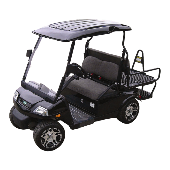
- Page 1 2016 Owner’s Manual T- SPORT ® Neighborhood Electric Vehicle (NEV) Electric Low Speed Vehicle (LSV) This Manual is effective as of November 1, 2015...
-
Page 2: Notice
ACG is not liable for any additional requirements or modifications that your individual state may require. ACG is not liable of errors in this manual or for incidental or consequential damages that result from the use of the material in this manual. -
Page 3: Table Of Contents
ABOUT THIS MANUAL…………………………………………………………..…… 5 SAFETY PRECAUTIONS (EV)................6 Insurance Notice…………………………………………………………………...…… 7 Warranty Registration……………………………………………………………...…… 7 General Warnings…………………………………………………………………...….. 8 SAFE OWNERSHIP OF ACG NEV………………………………………………..…. 10 Cautions, Warnings and Notes……………………………………………………..… 11 Driving and Alcohol....................12 Safety Information....................13 Roll over Warning....................15 Controls and Indicators…………………………………………………………..….…. -
Page 4: Foreword
Foreword Thank you for choosing the T-SPORT NEV for your local and community ® transportation needs. Please protect your investment to make sure that your T-SPORT NEV will provide ® you with years of reliable performance. Your safety is important to us, so please make sure that prior to operating the vehicle you have read the following instructions and warnings. -
Page 5: Introduction
For the latest version please visit www.acgcars.us, and click on About ACG, Current ACG Owners, and Owners Manuals. Then select the Model and Model Year of your vehicle. -
Page 6: Safety Precautions (Ev)
If exposed electric wires are visible inside or outside of your vehicle, an electric shock may occur. Never touch the electric wires. If you discover a leak or damage to any traction battery, contact a ACG Dealer immediately. Never touch fluid leaks inside or outside the vehicle. -
Page 7: Insurance Notice
ACG and its dealers shall not be liable for loss of use, inconvenience, lost time, commercial loss or any incidental, consequential or other damages. A separate “Tire Registration Card”... -
Page 8: General Warnings
General Warnings 1. This “Owner’s Manual” should be read completely before attempting to drive or service the vehicle. Failure to follow the instructions in this manual could result in property damage, severe personal injury, or death. 2. When charging the vehicle, be sure that the key switch is in the “OFF” position. If the key is left in the “ON“... - Page 9 WARNING! You can be badly injured working on an electric vehicle. Take your vehicle to your ACG dealer or call ACG Customer Service at (909) 597-2885 for your service needs. Page 9 Copyright © 2012-2015 American Custom Golf Cars, Inc.
-
Page 10: Safe Ownership Of Acg Nev
15 Ampere electrical outlet that is ground-fault protected. Charging from a circuit of lesser capacity and/or using a cord from the outlet to the ACG vehicle that is not sufficient in wire gauge (AWG) could create a fire hazard. Please consult “Charging Procedures Manual” for the proper extension cord gauge which depends on its length. -
Page 11: Cautions, Warnings And Notes
• The voltage in an ACG vehicle battery pack (the battery pack is what you charge and provides the “fuel” to the ACG’s electric drive system) is 48 Volt DC and is sufficient to cause death by electric shock - electrocution. -
Page 12: Driving And Alcohol
Driving and Alcohol Your ability to drive your ACG vehicle can be seriously impaired with blood alcohol levels far below the legal minimum. If you are drinking alcohol, don’t drive. Ride with a designated non-drinking driver, call a cab, or use public transportation. -
Page 13: Safety Information
Follow all instructions carefully when dealing with batteries. • The batteries in the ACG NEV are six (6) 8-Volt lead acid batteries. They are however connected in a pack configuration to produce HIGH VOLTAGE DC (48 volts). - Page 14 Avoid contact with skin, eyes or clothing. • Batteries contain acid, which can cause severe burns. If battery fluid comes in contact with your skin, flush the affected areas with water for at least 15 minutes and then seek medical assistance. •...
-
Page 15: Roll Over Warning
Roll over Warning Because of the higher center of gravity and the narrower track of this vehicle, it may roll over when some other vehicles may not. Do not attempt sharp turns or abrupt maneuvers or other unsafe driving actions that can cause loss of vehicle control and possible roll over. Failure to operate this vehicle safely may result in an accident, roll over, and serious injury or death. -
Page 16: Controls And Indicators
Controls and Indicators Key Switch The “Key Switch” is mounted on the dash to the right of the steering column. It has two positions: 1. OFF position- There is no power to vehicle. ( Key is Vertical as shown in picture below 2. -
Page 17: Direction Control Switch (D-N-R)
Direction Control Switch The “Direction Control Switch” is a 3 position “rocker” switch that is located on the vehicle dash panel to the right of the vehicle center and to the right of the “ Lights Switch”. The switch is labeled “Direction”. There are three (3) distinct positions: and so indicated on label to the Right of the switch. - Page 18 CAUTION! Always bring the vehicle to a complete stop before changing the position of the “Direction Control Switch”. IMPORTANT! The vehicle “ MUST be initially in the neutral Direction Control Switch” central position when you first turn the “Key Switch” to the “ON” position;...
-
Page 19: Accelerator Pedal
Accelerator Pedal The “Accelerator Pedal” is the pedal on the right, with the word “GO” molded into it. The operation of the accelerator pedal differs from that of an Automobile. When the “Key Switch” is in the “ON” position, depressing the accelerator pedal will release the parking brake. -
Page 20: Brake Pedal
Brake Pedal The “Brake Pedal” is the large pedal on the left with the word “STOP” molded into it. To slow or stop the vehicle, release the “Accelerator Pedal” and then depress the brake pedal with your foot until the NEV has come to a complete stop or the vehicle has slowed to your desired speed. -
Page 21: Light Switch
Light Switch The “Light Switch” turns the headlights and taillights on and off. The “Light Switch” is located on the Dashboard to the right of the steering column and to the right of center of the dashboard and to the left of the “Direction Control Switch”. -
Page 22: Turn Signal Lever Switch
Turn Signal Lever Switch The Turn Signals are activated by Lever Switch located on Left side of steering column below Steering Wheel. It is a 3 position switch. 1.) RIGHT - When the Lever is pushed UP ( ) – the Right Lights Flash. Clockwise 2.) OFF - When the Lever is Horizontal, the Turn Signal lights are “OFF”. -
Page 23: Turn Signal Directional Indicators
Turn Signal Directional Indicators GREEN Light on Left of the Display will flash when Left Turn Signal is activated (as shown above). GREEN Light on Right of the Display will flash when Right Turn Signal is activated ... -
Page 24: Display Panel
Display ® The T-SPORT NEV LCD display has following functions: Battery State of Charge (SoC) shown on bar graph at right of the screen and as percent % at top of the bar graph (shown above as 88%) Trip Distance Traveled in miles in NN.N format (shown above as 90.6 mi.) ... -
Page 25: Display Panel Other Functions
Display Screen – Other Functions Main Screen Main screen will display Direction, Speed and Battery Charge Level both on Bar Graph as well as in Percent (%) of full charge, it also displays Trip (trip distance in miles since Trip meter re-set) and Odometer (total vehicle mileage traveled). - Page 26 Screen VEHICLE STATUS MONITOR Section A Battery shows Battery Nominal Voltage Trac Drive Status shows current status Section B Cont. Temp. (Controller Temperature) 2. Motor Volts 3. Motor Amps 4. Motor RPM (Rotations Per Minute) 5. Motor Torque in Percent (%) These values will change as soon as you start driving the vehicle.
- Page 27 Screen VEHICLE INPUTS MONITOR on this screen all switch and input signal conditions are displayed: Forward Reverse Seat Drv Select 1 Drv Select 2 Hand Brake Foot Brake Inch FWD sw Inch REV sw Note: Drive profile #2 (Drv Select 2) is only used for testing Purpose to see the Range of motor on the controller.
- Page 28 Screen TIME TO DISTANCE This screen displays the acceleration of the vehicle from 0-1000 feet and will automatically record the performance of the vehicle. It also displays the number of hours the vehicle was driven. [8 ] To proceed to a 4 Screen push center arrow button once.
- Page 29 Screen FAULT LOG Log of all faults that have ever possibly occurred on the vehicle. The first 8 of the faults on the screen are fault checks which are created at the time the vehicle is the first programmed. button Any fault after that might be relevant.
- Page 30 Note: You will see a sequence fault if not started in neutral this code will clear as soon as you put the car in neutral. The vehicle will possibly give you a cut back code. When the vehicle gets low on power it will automatically cut back, this is a safety precaution to protect the motor and controller.
-
Page 31: Hazard Warning Flashers
Hazard Warning Flashers The Hazard Warning Flasher Switch activates both Turn Signals to provide “Hazard Warning” by flashing both Right and Left as well as Front and Rear Turn Signals at the same time. The “Hazard” function is activated by Pull Switch located on Left side of steering column below Steering Wheel. -
Page 32: Horn Button
Horn Button The Horn Button is located to the Left of the Brake Pedal (STOP/PARK) and is operated by the Left foot if audio warning is required during vehicle operation (see above). The switch is labeled “HORN”. It is also identified by SAE/ISO “Horn” icon. It is a momentary switch;... -
Page 33: Locking Glove Boxes
Locking Glove Boxes The T-SPORT ® NEV is equipped with two locking glove boxes on the dashboard. Both Locking Glove Boxes use the same key, which however is different from the “Key Switch”. You can safely lock your valuables in the glove boxes when you Valet park your vehicle. - Page 34 Damage to the vehicle electrical system may occur or an accessory fuse may blow. • The fuse for the power outlet plug is located in the fuse block. Always use fuses with the same type and rating. • Power outlets are designed for accessory plugs only. Do not hang any type of accessory or accessory bracket from the plug.
-
Page 35: Cup Holders
Cup Holders The upper center dash also contains two cup holders. CAUTION! Liquids can damage electrical components and the circuit board. Handle all liquids with care. Do not spray water directly into the upper or lower dash. Page 35 Copyright © 2012-2015 American Custom Golf Cars, Inc. -
Page 36: Safety Belts
Safety Belts Your T-SPORT ® NEV is equipped with “Safety Belts” for both driver and all passengers. Research has shown that safety belts save lives. Safety belts can reduce the seriousness of injuries in a single vehicle accident. Some of the worst injuries happen when people are thrown from the vehicle. - Page 37 Proper Use of Seat Belt Enter the vehicle and sit back. Grasp the safety belt buckle and slide the buckle up the webbing as far as necessary to make the belt go around your lap and across you chest. When the safety belt is long enough to fit, insert the buckle into the latch until you hear a click.
- Page 38 SEAT BELTS AND PREGNANT WOMEN We recommend that pregnant women use seat belts throughout their pregnancy. Keeping the mother safe is the best way to keep the baby safe. Pregnant women should wear the lap part of the belt across the thighs and as snug across the hips as possible.
- Page 39 Child Restraint Everyone in your vehicle needs to be buckled up at all times - babies and children, too. Every state in the United States and all Canadian provinces require that small children ride in proper restraint systems. This is the law, and you can be prosecuted for ignoring it.
- Page 40 Infants and Child Restraints Safety experts recommend that children ride rearward-facing in the vehicle until they are at least one year old and weigh at least 20 lbs (9 kg). Two types of child restraints can be used rearward-facing: infant carriers and “convertible”...
- Page 41 Before buying any restraint system, make sure that it has a label certifying that it meets all applicable Safety Standards. ACG also recommends that you try a child restraint in the vehicle seats where you will use it before you buy it.
-
Page 42: Transporting Pets
Pets should be restrained in a pet harness, or in a pet carrier that is secured by seat belt. Optional Accessories CAUTION! Use only ACG approved accessories. Others may cause damage to the vehicle, and will void warranty. WARNING! Any modifications or alterations to this vehicle could seriously affect its road worthiness and safety and may lead to an accident resulting in serious injury or death. -
Page 43: Tires & Wheels
4. Wear Any accelerated wear of tires may be an indicator of improper alignment or poor driving habits. If uncertain, consult your ACG service provider. NOTE: The vehicle’s tire information can be found on the “Tire Information Label”... - Page 44 The tires on your new vehicle provide a balance of many characteristics. They should be inspected regularly for wear and correct inflation pressure. ACG strongly recommends that you use tires equivalent to the originals in quality and performance when replacement is needed. Failure to use equivalent replacement tires may adversely affect the safety, handling, and ride of your vehicle.
- Page 45 WARNING! • Do not use a tire, wheel size or rating other than that specified for your vehicle. • Some combinations of unapproved tires and wheels may change suspension dimensions and performance characteristics, resulting in changes to steering, handling, and braking of your vehicle. This can cause unpredictable handling and stress to steering and suspension components.
-
Page 46: Tire Changing And Jacking Points
Tire Changing & Jacking Points In the event of a flat tire, you need to observe the following precautions: Park the vehicle on a firm level surface; avoiding icy or slippery areas. Set the parking brake and block both the front and rear of the tire diagonally opposite the jacking position. -
Page 47: Consumer Information (Tires)
Consumer Information (Tires) 'Consumer Tire Guide' For further information, the on passenger tire care, safety and mileage performance is available in the United States by writing Tire Industry Safety Council Box 1801 Washington, D.C. 20013 For more information on the Tire Industry Safety Council, please consult the following:... -
Page 48: Brakes
If the Brake Fluid needs to be refilled more frequently than every other month then check the entire Brake System for any leakage and see your dealer for service or call immediately ACG Customer Service at (909) 597-2885 Page 48... - Page 49 CAUTION! Brake fluid may cause damage to painted and finished surfaces. Use caution when refilling the brake fluid reservoir. CAUTION! Use only DOT 4 Brake Fluid from a sealed Container. Clean Filler Cap before removing. Page 49 Copyright © 2012-2015 American Custom Golf Cars, Inc.
-
Page 50: Pre-Operation And Daily Safety Checklist
Pre-Operation and Daily Safety Checklist Every T-SPORT ® NEV is thoroughly inspected and adjusted at the factory and again re-inspected by your ACG Dealer before it arrives at your door. However, upon receiving your new T-SPORT ® NEV you should take time to become familiar with its controls and operation. -
Page 51: Performance Inspection
Performance Inspection After you have familiarized yourself with the operation of all the controls of the T-SPORT ® NEV and have read and understood the driving instructions, take the vehicle for a test drive. Use the following checklist as a guide to inspect the vehicle and check daily for proper operation. -
Page 52: Driving Instructions
Driving Instructions WARNING! No person should be allowed to operate the vehicle without being instructed in the proper use and operation of the vehicle’s controls. Each first time driver should be accompanied by an experienced driver on a test drive before being allowed to operate the vehicle alone. 1. - Page 53 13. To prevent the vehicle from overturning, drive slowly straight up and down slopes. Slope exceeding 20% incline should be avoided. 14. Avoid sudden stops, sudden starts, and abrupt turns to prevent possible injury to an inattentive passenger or damage to the vehicle. 15.
-
Page 54: Starting The Vehicle
Starting the Vehicle 1. Study and understand controls. 2. Make sure everyone is seated with all parts of their body inside the vehicle. 3. Make sure everyone’s “Seat Belts” are properly fastened. 4. Make sure front wheels are turned in the desired travel direction. 5. -
Page 55: Batteries
Batteries Your T-SPORT ® is operated as a 48-Volt unit with six (6) 8-Volt batteries. The batteries are specially designed and produced for use in an electric vehicle. If the batteries need to be replaced at any time for any reason, do not use automotive batteries. -
Page 56: Battery Inspection & Maintenance
Battery Inspection & Maintenance Inspection There are many tools that may help in properly caring for and maintaining batteries. Below is a list of basic items that ACG recommends for this task: Recommended Equipment: Wrench Post Cleaner ... -
Page 57: Cleaning
4. Tighten all wiring connections to the proper specification (see below). Make certain there is good contact with the terminals. Proper Torque Values for Connection Hardware: Flooded Side 70-90 in-lbs Wing nut 95-105 in-lbs LPT 95-105 in-lbs Stud 120-180 in-lbs LT 100-120 in-lbs VRLA Button 90 to 100 in-lbs... -
Page 58: Watering
Keeping the water at the correct level after a full charge will prevent having to worry about the water level at a different state of charge. Depending on the local climate, charging methods, application, etc. ACG recommends that batteries be checked once a month until you get a feel for how thirsty your batteries are. - Page 59 Step by step watering procedure: 1. Open the vent caps and look inside the fill wells. 2. Check electrolyte level; the minimum level is at the top of the plates. 3. If necessary add just enough water to cover the plates at ...
-
Page 60: Charging Batteries
Charging Batteries CAUTION! Be sure that the “Key Switch” is in the “OFF” position prior to charging. 1. Your vehicle is equipped with an on board charger. To begin charging the batteries, insert a UL approved 3 prong extension cord into any household 110-Volt AC 15-Amp outlet and plug the other end into the charging cord receptacle located at center below the Front Seats. -
Page 61: Battery Replacement
Contact local and/or state environmental officials regarding disposal information. You can also contact ACG Customer Service at (909) 597-2885 for information. Page 61 Copyright © 2012-2015 American Custom Golf Cars, Inc. - Page 62 Additional Battery Service Warnings & Cautions WARNING! Always wear safety glasses or approved eye protection when servicing the vehicle. Wear a full-face shield and gloves when working with or around batteries and electrical connectors. Always use insulated tools when working with or near batteries. ...
-
Page 63: Charging Procedures
Charging Procedures GENERAL WARNINGS This “Charging Procedures” section should be read completely before attempting to charge or service the vehicle. Failure to follow the instructions in this manual could result in property damage, severe personal injury, or death. 1.) When charging the vehicle, be sure that the “Key Switch” is in the “OFF” position. - Page 64 VEHICLE CHARGING Follow the recommended “step-by-step” procedure below to re-charge the vehicle. MAIN KEY SWITCH Turn the key switch located to the right of the Steering Column counter- clockwise to the “OFF” position (vertical). (As Shown in Picture below) The “Key Switch” is mounted on the dash to the right of the steering column. It has two positions: 1.
- Page 65 ARKING RAKE Fully apply the parking brake by depressing the portion of the Brake Pedal (STOP) that is labeled “PARK”. Verify that the Brake Pedal is in locked (PARK) position and the vehicle is stationary. WARNING! The “Park Brake” will release automatically when either the “Accelerator Pedal”...
- Page 66 Direction Control Switch The “Direction Control Switch” is a 3 position “rocker” switch that is located on the vehicle dash panel to the right of the vehicle center-line and to the right of the “Lights Switch”. The switch is labeled “Direction”. There are three (3) distinct positions: and so indicated on label to the Right of the switch.
- Page 67 AC Cord 4. Plug the AC Extension Cord into the vehicle charging inlet socket located at the center of the vehicle under the Front seats. CAUTION: AC Extension Cord must be of suitable length and proper AWG. (See Table T on Page 68 for proper AWG wire size) Plug the other end of the AC Extension Cord into 120V AC 3-conductor (Grounded) 120V AC household socket that is fused at a minimum of 15 Amp;...
- Page 68 Kill- 5. Plug the other end of the extension cord into front of the A-Watt Meter Kill- 6. Plug the A-Watt Meter into 120V AC household socket that is fused at a minimum of 15 Amp; 20 Amp circuit is preferable if available. AVOID connecting any other device or appliance into the same 15A/20A circuit or the circuit may become overloaded, which will result in tripping...
- Page 69 48 V SYSTEM CHARGER (TRACTION Batteries) a.) Lift the Front Bench seat by grabbing either Right or Left handlebar at the top as shown below and indicated by b.) The Seat will rotate on the hinge that is installed at the Front of the seat cushion.
- Page 70 Check the Charger LED display a.) verify that the charger ON telltale LED (~) on the Charger is lighted. Condition YELLOW = ON b.) verify that one of the charger charge rate telltale LEDs ( I – IIIIII ) on the Charger is lighted ...
- Page 71 Charger ON (Start of Charge) NOTE: If the Traction Battery is fully depleted the 48 V SYSTEM CHARGER will remain in the Minimum Charge rate mode (Yellow LED I Lighted) for several minutes, if the Traction Battery is not fully depleted, the Charger will automatically switch to the Maximum Charge Rate Mode (Yellow LED IIIIII lighted) in just few seconds.
- Page 72 If the charging rate is reduced due to state of battery charge, one of the Yellow LEDs in the upper Six LED Ammeter section will be ON. The Yellow LED with SIX bars (IIIIII) indicates Maximum Rate of Charge – Charger power input of about 10 to 11 Amperes @ 120 V AC. The Yellow LED with ONE bar (I) indicates Minimum Rate of Charge –...
- Page 73 Charger ON (Min rate of Charge) (80% state of Charge) When Absorption charge phase is completed and the charger now enters the Finish charge phase Green LED indicating “End of Charge” charge will be Flashing. When the “100% state of Charge” is reached the Green LED indicating “End of Charge”...
- Page 74 VEHICLE CHARGING ( End of Charge ) Follow the recommended step-by-step procedure after vehicle was re- charged. 48 V SYSTEM CHARGER (TRACTION Batteries) - a.) verify that the charger ON telltale LED (~) on the Charger is lighted. Condition YELLOW = ON ...
- Page 75 P3 - KILL A WATT Operation Manual 1. The LCD shows all meter readings: Volts, Current, Watts, Frequency, Power Factor, and VA. The unit will start to accumulate kWh and powered duration time (hours & minutes) after power is applied. 2.
- Page 76 WARNING! Do not exceed maximum ratings as detailed on label. Button 1 = Volt Button 2 = Amp Button 3 = Watt / VA (toggle) Button 4 = Hz / PF (toggle) Button 5 = kWh / TIME (toggle) Page 76 Copyright ©...
-
Page 77: Periodic Maintenance
Periodic Maintenance DAILY TASKS 1. Charge Batteries fully before first use of vehicle. 2. Check battery terminals for tight connections. 3. Visually inspect the tires for wear, damage, and proper inflation. 4. Check for proper operation of parking brake. 5. Check seat belts for proper operation. Page 77 Copyright ©... -
Page 78: Monthly Tasks
Periodic Maintenance MONTHLY TASKS 1. Check all six (8 Volt) Flooded batteries for proper water level. Use only Distilled Water for addition. (Not necessary if vehicle is equipped with Sealed or maintenance free Gel batteries). 2. Check battery terminals for tight connections. 3. -
Page 79: Cleaning
® NEV as it is made from safety glass. ACG recommends using Windshield Washer Fluid to remove normal dust and dirt. A liquid household glass cleaner can also be used. Do not use abrasive cleaners on the windshield, as they will cause scratches. - Page 80 It is recommended to protect the vehicle whenever possible and preferably to store it indoors during extended non-use periods. ACG Custom Vehicle Cover is available at ACG dealerships. Page 80 Copyright © 2012-2015 American Custom Golf Cars, Inc.
-
Page 81: Transport Or Towing
Use Tie-Down points on the frame identified with an “X” as shown on page NOTE: ACG is not responsible for damage incurred or lost items due to vehicle towing. CAUTION! TOWING THE VEHICLE IS NOT RECOMMENDED. This vehicle is not designed for dolly towing. -
Page 82: Floor Mat Safety Information
Floor Mat Safety Information Always use floor mats designed to fit the footwell of your vehicle. Use only floor mats that leave the pedal area unobstructed and that are firmly secured so that they cannot slip out of position and interfere with the pedals or impair safe operation of your vehicle in other ways. -
Page 83: Consumer Information
Consumer Information §575.6 Consumer Information Regulations; Requirements as per 49 CFR Part 575.6 Reporting Safety Defects If you believe that your vehicle has a defect which could cause a crash or could cause injury or death, you should immediately inform the National Highway Traffic Safety Administration (NHTSA) in addition to notifying American Custom Golf Cars, Inc. -
Page 84: Specifications
Specifications Make Model T-SPORT ® Type NEV (Neighborhood Electric Vehicle) Emission Category ZEV (Zero Emission Vehicle) Fuel Category BEV (Battery-powered) Test Group FACGV000.0NEV Overall Length Inches ( with Back Step Overall Width 42 ½ Inches Height to top of Windshield Inches Wheelbase 65 ½... - Page 85 Manufactured by: American Custom Golf Cars, Inc. (ACG) 15740 El Prado Rd. Chino, CA 91710 USA (909) 597-2885 (909) 597-7183 fax www.acgcars.us Copyright © 2012-2015 American Custom Golf Cars, Inc. ACG Logo: T-SPORT ® Are registered trademarks of American Custom Golf Cars, Inc.
Need help?
Do you have a question about the T-SPORT NEV 2016 and is the answer not in the manual?
Questions and answers