Advertisement
Table of Contents
- 1 Table of Contents
- 2 Warning Decal Placement
- 3 Important Precautions
- 4 Before You Begin
- 5 Part Identification Chart
- 6 Assembly
- 7 The Chest Heart Rate Monitor
- 8 How to Use the Exercise Bike
- 9 Fcc Information
- 10 Maintenance and Troubleshooting
- 11 Exercise Guidelines
- 12 Part List
- 13 Exploded Drawing
- 14 Ordering Replacement Parts
- 15 Limited Warranty
- Download this manual
www.nordictrack.com
Model No. NTEX07912.1
Serial No.
Write the serial number in the
space above for reference.
Serial Number
ACTIVATE YOUR
WARRANTY
To register your product and
activate your warranty today, go
to www.nordictrackservice.com/
registration.
CUSTOMER CARE
For service at any time, go to
www.nordictrackservice.com.
Or call 1-800-TO-BE-FIT
(1-800-862-3348)
Mon.––Fri. 6 a.m.––6 p.m. MT
Sat. 8 a.m.––4 p.m. MT
Please do not contact the store.
CAUTION
Read all precautions and instruc-
tions in this manual before using
this equipment. Keep this manual
for future reference.
Decal
USER’'S MANUAL
Advertisement
Table of Contents

Subscribe to Our Youtube Channel
Related Manuals for NordicTrack VR Pro NTEX07912.1


Summary of Contents for NordicTrack VR Pro NTEX07912.1
- Page 1 Model No. NTEX07912.1 Serial No. USER’’S MANUAL Write the serial number in the space above for reference. Serial Number Decal ACTIVATE YOUR WARRANTY To register your product and activate your warranty today, go to www.nordictrackservice.com/ registration. CUSTOMER CARE For service at any time, go to www.nordictrackservice.com.
-
Page 2: Table Of Contents
If a decal is missing or illegible, see the front cover of this manual and request a free replacement decal. Apply the decal in the location shown. Note: The decal(s) may not be shown at actual size. NORDICTRACK is a registered trademark of ICON IP, Inc. -
Page 3: Important Precautions
IMPORTANT PRECAUTIONS WARNING: To reduce the risk of serious injury, read all important precautions and instructions in this manual and all warnings on the exercise bike before using the exercise bike. ICON assumes no responsibility for personal injury or property damage sustained by or through the use of this product. - Page 5 STANDARD SERVICE PLANS...
-
Page 6: Before You Begin
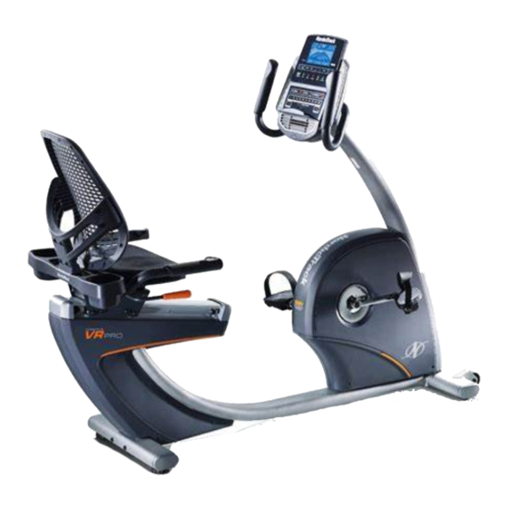
BEFORE YOU BEGIN Thank you for selecting the revolutionary reading this manual, please see the front cover of this NORDICTRACK COMMERCIAL VR PRO exercise manual. To help us assist you, note the product model ® bike. Cycling is an effective exercise for increasing number and serial number before contacting us. -
Page 7: Part Identification Chart
PART IDENTIFICATION CHART Use the drawings below to identify the small parts needed for assembly. The number in parentheses below each drawing is the key number of the part, from the PART LIST near the end of this manual. The number following the key number is the quantity needed for assembly. -
Page 8: Assembly
ASSEMBLY •• Assembly requires two persons. In addition to the included tool(s), assembly requires the following tools: •• Place all parts in a cleared area and remove the one Phillips screwdriver packing materials. Do not dispose of the packing materials until you nish all assembly steps. one adjustable wrench ••... - Page 9 3. Set a sturdy piece of packing material under the front of the Frame (1). Have a second person Wheel hold the Frame to prevent it from tipping while you complete this step. Orient the Front Stabilizer (15) as shown. Attach the Front Stabilizer to the Frame (1) with two M10 x 122mm Screws (65).
- Page 10 5. Tip: Avoid pinching the wires. Slide the Upright (2) onto the Frame (1). Attach the Upright (2) with four M10 x 62mm Screws (70); start all the Screws, and then tighten them. Avoid pinching the wires 6. Press the mount on the Front Shield (58) into the Frame (1).
- Page 11 7. Orient the Upright Cover (57) as shown. Hold the Upright Cover near the Upright (2), and insert the wires upward through the Upright Cover. Then, slide the Upright Cover (57) onto the Wire Tie Upright (2). Wires 8. While a second person holds the Handlebar (7) near the Upright (2), insert the wires upward through the Handlebar.
- Page 12 10. Tip: Avoid pinching the wires. Attach the Console (4) to the Handlebar (7) with four M4 x 16mm Screws (77). Avoid pinching the wires 11. Attach the Upright Cover (57) to the Handlebar (7) with two M4 x 16mm Screws (77). 12.
- Page 13 13. Slide the Accessory Tray (56) onto the Seat Handlebar (10). Attach the Accessory Tray (56) to the Seat Handlebar (10) with four M4 x 16mm Screws (77). 14. Orient the Seat (9) as indicated by the sticker. Attach the Seat (9) to the Seat Handlebar (10) with four M6 x 18mm Screws (25) and four M6 Washers (88) (only two of each are shown);...
- Page 14 15. Slide the Backrest Back (81) onto the Seat Handlebar (10). Attach the Backrest Back (81) with four M6 x 30mm Screws (75) and four M6 Washers (88); start all the Screws, and then tighten them. 16. Identify the Right Pedal (21). Using an adjustable wrench, firmly tighten the Right Pedal (21) clockwise into the Right Crank Arm (23).
- Page 15 17. Plug the Power Adapter (51) into the receptacle on the frame of the exercise bike. Note: To plug the Power Adapter (51) into an outlet, see HOW TO PLUG IN THE POWER ADAPTER on page 17. 18. After the exercise bike is assembled, inspect it to make sure that it is assembled correctly and that it functions properly.
-
Page 16: The Chest Heart Rate Monitor
THE CHEST HEART RATE MONITOR HOW TO PUT ON THE HEART RATE MONITOR •• Do not expose the heart rate monitor to direct sun- light for extended periods of time; do not expose it to The heart rate temperatures above 122° F (50° C) or below 14° F monitor consists of (-10°... -
Page 17: How To Use The Exercise Bike
HOW TO USE THE EXERCISE BIKE HOW TO PLUG IN THE POWER ADAPTER HOW TO ADJUST THE PEDAL STRAPS IMPORTANT: If the exercise bike has been exposed To adjust the pedal to cold temperatures, allow it to warm to room straps, ... - Page 18 CONSOLE DIAGRAM FEATURES OF THE CONSOLE The console also features an iFit mode that enables the console to communicate with your wireless net- The advanced console offers an array of features work through an iFit module. With the iFit mode, you designed to make your workouts more effective and can download personalized workouts, create your enjoyable.
- Page 19 HOW TO USE THE MANUAL MODE Calories per Hour (Calories/Hr)——This display mode will show the approximate number of calories 1. Begin pedaling or press any button on the you are burning per hour. console to turn on the console. Distance (Dist.)——This display mode will show When you turn on the console, the display will turn the distance that you have pedaled in miles or on.
- Page 20 Press the Home button to return to the default When your pulse is detected, a heart symbol will menu (see HOW TO CHANGE CONSOLE flash in the display each time your heart beats, SETTINGS on page 25 to set the default menu). one or two dashes will appear, and then your heart If necessary, press the Home button again.
- Page 21 HOW TO USE AN ONBOARD WORKOUT resistance level and/or target speed is programmed for the next segment, the resistance level and/or 1. Begin pedaling or press any button on the target speed will appear in the display for a few console to turn on the console.
- Page 22 HOW TO USE A SET-A-GOAL WORKOUT Note: If you manually change the resistance during a calorie goal workout, the length of the workout 1. Begin pedaling or press any button on the will adjust automatically to ensure that you meet console to turn on the console.
- Page 23 HOW TO USE AN IFIT WORKOUT Press the Compete button to compete in a race that you have previously scheduled. 1. Begin pedaling or press any button on the console to turn on the console. Press the Track button to re-run a recent iFit work- out from your schedule.
- Page 24 6. Follow your progress with the display. 8. Turn on the fan if desired. See step 4 on page 19. See step 6 on page 20. The My Trail tab will show a map of the trail you are 9. When you are finished exercising, the console walking or running or it will show a track and the will turn off automatically.
- Page 25 HOW TO CHANGE CONSOLE SETTINGS If no module is connected, the display will show the words NO IFIT MODULE. If no module is con- The console features a user mode that allows you to nected, go to step 10. view usage information, select a unit of measurement, and adjust the contrast level of the display.
-
Page 26: Fcc Information
FCC INFORMATION This equipment has been tested and found to comply with the limits for a Class B digital device, pursuant to part 15 of the FCC Rules. These limits are designed to provide reasonable protection against harmful interference in a residential installation. This equipment generates, uses, and can radiate radio frequency energy and, if not installed and used in accordance with the instructions, may cause harmful interference to radio communications. -
Page 27: Maintenance And Troubleshooting
MAINTENANCE AND TROUBLESHOOTING Inspect and tighten all parts of the exercise bike regu- Note: For clarity, the Right Shield is not shown in the larly. Replace any worn parts immediately. drawing below. To clean the exercise bike, use a damp cloth and a Locate the Reed Switch (46). - Page 28 HOW TO ADJUST THE DRIVE BELT Loosen the M6 x 20mm Hex Screw (84). Tighten the M10 x 50mm Hex Screw (83) until the Drive Belt (47) If the pedals slip while you are pedaling, even while the is tight. When the Drive Belt is tight, tighten the M6 x resistance is adjusted to the highest setting, the drive 20mm Hex Screw.
-
Page 29: Exercise Guidelines
EXERCISE GUIDELINES Burning Fat——To burn fat effectively, you must exer- WARNING: cise at a low intensity level for a sustained period of Before beginning this time. During the first few minutes of exercise, your or any exercise program, consult your physi- body uses carbohydrate calories for energy. - Page 30 SUGGESTED STRETCHES The correct form for several basic stretches is shown at the right. Move slowly as you stretch; never bounce. 1. Toe Touch Stretch Stand with your knees bent slightly and slowly bend forward from your hips. Allow your back and shoulders to relax as you reach down toward your toes as far as possible.
- Page 31 NOTES...
-
Page 32: Part List
PART LIST Model No. NTEX07912.1 R0613A Key No. Qty. Description Key No. Qty. Description Frame Reed Switch/Wire Upright Drive Belt Foot Stabilizer Cap Console Left Handlebar Grip Rail Flange Screw Adjustment Bar Power Adapter Handlebar Shield Disc Backrest Heart Rate Monitor Seat Chest Strap Seat Handlebar/Wire... - Page 33 Key No. Qty. Description Key No. Qty. Description M8 Split Washer Left Rear Shield Crank Cap Small M6 Washer M6 Locknut Mechanism Spacer Tree Fastener –– Assembly Tool Steel Washer –– User’’s Manual M6 Split Washer –– Module Right Rear Shield ––...
-
Page 34: Exploded Drawing
EXPLODED DRAWING A Model No. NTEX07912.1 R0613A... - Page 35 EXPLODED DRAWING B Model No. NTEX07912.1 R0613A...
-
Page 36: Ordering Replacement Parts
ORDERING REPLACEMENT PARTS To order replacement parts, please see the front cover of this manual. To help us assist you, be prepared to provide the following information when contacting us: •• the model number and serial number of the product (see the front cover of this manual) ••...
Need help?
Do you have a question about the VR Pro NTEX07912.1 and is the answer not in the manual?
Questions and answers