Vivotek SD8362E Quick Installation Manual
20x zoom?2mp?full hd
Hide thumbs
Also See for SD8362E:
- User manual (192 pages) ,
- Specification (2 pages) ,
- Installation manual (10 pages)

Subscribe to Our Youtube Channel
Related Manuals for Vivotek SD8362E


Summary of Contents for Vivotek SD8362E
- Page 1 Quick Installation Guide Türkçe Deutsch Italiano Русский Česky Svenska English Français Español Português Polski 繁中 簡中 日本語 SD8362E 20x Zoom‧2MP‧Full HD...
- Page 2 Warning Before Installation Power off the Network Camera as Refer to your user’s manual for the soon as smoke or unusual odors are operating temperature. detected. Contact your distributor in the event of occurrence. Do not touch the Network Camera Do not disassemble the Network during a lightning storm.
-
Page 3: Package Contents
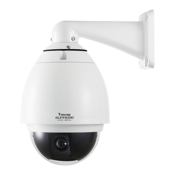
Package Contents SD8362E Wall Mount Bracket O-ring and Screws / Moisture Absorber / Metal Ring Alignment Sticker Quick Installation Guide RJ45 Female/Female Coupler Quick Installation Guide English 繁中 簡中 日本語 Français Español Deutsch Português Italiano Türkçe Polski Русский Česky Svenska SD8362E 20x Zoom•2MP•Full HD... -
Page 4: Physical Description
Physical Description Inner View SD/SDHC Card Slot Status LED Reset Button Lens Outer View DO2- General I/O DO1- Terminal Block Ethernet 10/100 RJ45 Plug Audio Out (green) Microphone In (pink) Power Cord Socket (black) Ground EN-3... - Page 5 Hardware Installation Mounting the Network Camera 1. Attach the alignment sticker to the wall. 2. Drill four pilot holes into the wall. 3. Attach the black cover to the Network Camera using the supplied four black screws. 4. Stick the supplied two pieces of moisture absorber symmetrically to the inner side of the dome cover.
- Page 6 Network Deployment General Connection (without PoE Plus) 1. If you have external devices such as sensors and alarms, connect them to the general I/O terminal block. GND: Ground 2. Use the supplied RJ45 female/female DO2: Digital Output 2 DO2- coupler to connect the Network Camera DO1- DO1: Digital Output 1 to a switch.
-
Page 7: Assigning Ip Address
"Next" button to continue the program. Installation Wizard 2 3. The program will search for VIVOTEK Video Receivers, Video Servers, and Network Cameras on the same LAN. 4. After a brief search, the main installer window will pop up. Double-click on the MAC address that matches the one printed on the camera label or the S/N number on the package box label to open a browser management session with the Network Camera. -
Page 8: Ready To Use
Ready to Use 1. A browser session with the Network Camera should prompt as shown below. 2. You should be able to see live video from your camera. You may also install the 32- channel recording software from the software CD in a deployment consisting of multiple cameras. - Page 9 P/N: 625014300G Ver.1.0 Copyright 2011 VIVOTEK INC. All rights reserved.
Need help?
Do you have a question about the SD8362E and is the answer not in the manual?
Questions and answers