
Related Manuals for Vivotek FE8391-V


Summary of Contents for Vivotek FE8391-V
- Page 1 FE8391-V Fisheye Network Camera Quick Installation Guide Русский Česky Svenska Dutch 繁中 簡中 日本語 Türkçe Français Deutsch Italiano Polski English Español Português Indonesia Dansk 360° Surround View • 10M IR • PoE...
-
Page 2: Package Contents
Do not insert sharp or tiny objects into the Do not drop the Network Camera. Network Camera. Package Contents FE8391-V Mounting Plate / Screwdriver Alignment Stickers Screws / Desiccant Bag / Double-sided Tape / Rubber Seal... -
Page 3: Physical Description
Physical Description Inner View Lens Contacts (A) Header (J7) Contacts for IR units (B) Header (J6) Align (B) to (A) when attaching the dome cover Ethernet 10/100 RJ45 Socket Reset Button Status LEDs MicroSD/SDHC/SDXC Card Slot EN - 2... -
Page 4: Built-In Microphone
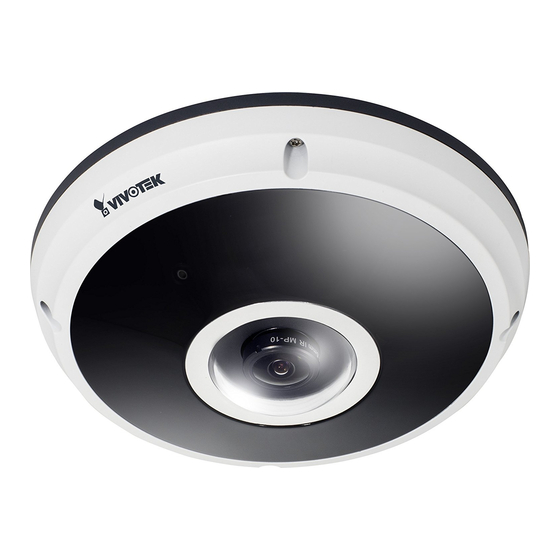
Outer View IP66-rated Vandal-proof Dome Cover Built-in Microphone IR lights hidden beneath panel IMPORTANT: Record the MAC address under the camera base before installing the 083236 camera. Hardware Installation First, use the supplied screwdriver to loosen the four screws and detach the dome cover from the camera base. -
Page 5: Connecting Dc Power Cable
Connecting RJ45 Ethernet Cable RJ45 Cable Dimension (unit: mm) Recommended cable gauge: (0.51 cm) Rubber Seal Plug Assembly Steps 1. Drill a hole on the rubber seal plug and in- sert an Ethernet cable through the opening. 2. Strip part of the sheath from the Ethernet cable. - Page 6 Ceiling/Wall Mount without Mounting Plate (Choose this mounting type if you want to feed the cables form the bottom of the camera) 1. Attach the supplied alignment sticker for camera base to the ceiling/wall. 2. Using the three circles on the sticker, drill three pilot holes into the ceiling. Then hammer the three supplied plastic anchors into the holes.
- Page 7 Ceiling/Wall Mount with Mounting Plate (Choose this mounting type if you would like to feed the cables form the side) 1. Attach the supplied alignment sticker for the supplied mounting plate to the ceiling/wall. 2. Using the three circles on the sticker, drill three holes into the ceiling. Then hammer the three supplied plastic anchors into the holes.
-
Page 8: Network Deployment
You may also use the diagonal holes on the mounting plate, marked as A, B, or C, to install the camera to a standard 4 in. junction box. Network Deployment General Connection (without PoE) 1. Connect RJ45 Ethernet cable to a switch. 2. -
Page 9: Power Over Ethernet (Poe)
Power over Ethernet (PoE) When using a PoE-enabled switch The Network Camera is PoE-compliant, allowing transmission of power and data via a single Ether- net cable. Follow the below illustration to connect the Network Camera to a PoE-enabled switch via Ethernet cable. -
Page 10: Assigning An Ip Address
2. The program will conduct an analysis of your network environment. After your network is analyzed, please click on the “Next” button to continue the program. 3. The program will search for VIVOTEK Video Receivers, Video Servers, and Network Cameras on the same LAN. - Page 11 What VIVOTEK Will Do: VIVOTEK will, in our sole discretion, repair or replace any product that proves to be defective in material or workmanship. Any repair or replaced part of the product will receive a THREE-MONTH warranty extension.
- Page 12 P/N:625028801G Rev.: 1.1 All specifications are subject to change without notice. Copyright 2015 VIVOTEK INC. All rights reserved. VIVOTEK Europe Randstad 22-133, 1316BW Almere, The Netherlands T: +31(0)36-5298-434 E: saleseurope@vivotek.com...
Need help?
Do you have a question about the FE8391-V and is the answer not in the manual?
Questions and answers