Table of Contents
Advertisement
Quick Links
Owner/Operator Manual – Livret de l'opérateur/du propriétaire –
Betriebsanleitung – Manuale del proprietario/operatore –
Käyttöohjekirja – Manual del propietario/operador – Brukerhåndbok –
Instruktionsbok – Руководство владельца/пользователя – Instrukcja
Obslugi / Operatora – Mal Sahibi/Kullanici El Kitabi – Návod k obsluze/
pro obsluhu - Ръководство за работа за ползвателя/оператора -
Tulajdonosi/kezelői útmutató - Manualul proprietarului / operatorului -
Príručka majiteľa/obsluhy - Navodila za uporabo
ENGLISH
БЪЛГАРСКИ
ČESKY
SUOMI
FRANÇAIS
DEUTSCH
MAGYAR
ITALIANO
NORSK
POLSKI
ROMÂNĂ
РУССКИЙ ЯЗЫК
SLOVENSKY
SLOVENSKO
ESPAÑOL
SVENSKA
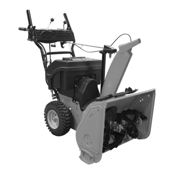
AMP 24
Sno-Thro
916302 – AMP 24
®
Model
03982615A 3/11
Printed in USA
Advertisement
Table of Contents

Related Manuals for Ariens 916302 amp 24 sno-thro


Summary of Contents for Ariens 916302 amp 24 sno-thro
- Page 1 AMP 24 Sno-Thro ® Owner/Operator Manual – Livret de l'opérateur/du propriétaire – Betriebsanleitung – Manuale del proprietario/operatore – Käyttöohjekirja – Manual del propietario/operador – Brukerhåndbok – Instruktionsbok – Руководство владельца/пользователя – Instrukcja Obslugi / Operatora – Mal Sahibi/Kullanici El Kitabi – Návod k obsluze/ pro obsluhu - Ръководство...
- Page 2 ES VYHLÁSENIE O ZHODE, VYDANÉ VÝROBCOM - ES-IZJAVA O SKLADNOSTI, KI JO JE IZDAL PROIZVAJALEC We the undersigned, ARIENS COMPANY, certify that: Nous, soussignés ARIENS COMPANY, certifions que : Der Unterzeichnete, ARIENS COMPANY, bescheinigt, dass: La sottoscritta società ARIENS COMPANY certifica che: Nosotros, los abajo firmantes, ARIENS COMPANY, certificamos que: Undertegnede, ARIENS COMPANY, bekrefter at: Undertecknad, ARIENS COMPANY, intygar att: Allekirjoittanut, ARIENS COMPANY, vakuuttaa, että: My, niŸej...
- Page 3 Datum Datum fichier technique) / Direktor Produktkonformität und Gewährleistung Dato Data (Aufbewahrungsstelle der technischen Dokumentation) / Directeur Fecha Dato Ariens Company Productconformiteit en -garantie (Beheerder technische Datum Brillion, WI 54110-0157 USA documentatie) / Direktør for varekonformitet og garanti og Päiväys Data Signature Signature Unterschrift reklamation (registeransvarlig) / Direttore della conformità...
-
Page 4: Table Of Contents
WARRANTY ..... 34 INTRODUCTION PRODUCT REGISTRATION Translation of original Instructions. The Ariens dealer must register the product MODEL AND SERIAL NUMBERS at the time of purchase. Registering the When ordering replacement parts or making... -
Page 5: Safety
NOTE: To locate your nearest Ariens Dealer, 5. Review Limited Warranty Policy. go to www.ariens.com on the Internet. 6. Fill out a Product Registration Card and return the card to the Ariens Company or go to www.ariens.com. SAFETY WARNING: To avoid injury to hands... - Page 6 SAFETY DECALS AND Wear appropriate hearing LOCATIONS protection. ALWAYS replace missing or damaged Safety Decals. Refer to figure below for Safety Decal OL4690 locations. ONLY use clean-out tool to clear blockages. NEVER use your hands. 2. DANGER! ROTATING PARTS! ONLY use clean-out tool to clear blockages.
- Page 7 ALWAYS check overhead and side DO NOT touch unit parts which might be hot clearances carefully before operation. from operation. Allow parts to cool before ALWAYS be aware of traffic when operating attempting to maintain, adjust or service. along streets or curbs. Never direct discharge towards persons or Keep children and people away.
- Page 8 Run auger a few minutes after clearing snow Poisonous battery fluid contains sulfuric acid. to prevent freeze-up. Contact with skin, eyes or clothing can cause severe chemical burns. Disengage attachment when not in use. Adjust skid shoes to clear gravel or crushed ALWAYS wear safety glasses and protective rock surfaces safely.
-
Page 9: Assembly
ASSEMBLY 2. Loosen the hardware on the shift rod. WARNING: AVOID INJURY. Read 3. Put the speed selector lever in the sixth forward position. and understand the entire Safety section before proceeding. 4. Rotate the handlebars into operating position. NOTE: Be careful not to damage cable spring WARNING: Dropping or tipping over hooks when rotating handlebars upward. - Page 10 Install Discharge Chute Figure 5 1. Grease underside of discharge chute ring (if not already greased). 2. Remove mounting hardware from the bottom of the chute pedestal. 3. Install discharge chute over opening in the auger housing and secure pedestal to auger housing with hardware removed in step 2.
- Page 11 1. Remote Deflector Cable 2. Remote Deflector Control 3. Cable Clip 4. Wire Cable Hook 5. Cable Mounting Bracket Figure 8 4. Pull rubber seal cap away from snap fitting. 5. Install snap fitting into cable bracket’s 1. Chute Crank upper mounting hole.
- Page 12 Check Tire Pressure Check tire pressure and adjust to the pressure listed on tire sidewall. CAUTION: Avoid injury! Explosive separation of tire and rim parts is possible when they are serviced incorrectly: • Do not attempt to mount a tire without the proper equipment and experience to perform the job.
-
Page 13: Controls And Features
CONTROLS AND FEATURES Figure 10 1. Attachment Clutch Lever 2. Speed Selector 3. Remote Deflector Lever 4. Traction Drive Clutch Lever 5. Chute Crank 6. Discharge Chute Deflector 7. Discharge Chute 8. Impeller 9. Auger 10. Scraper Blade 11. Auger Gearcase 12. -
Page 14: Operation
OPERATION IMPORTANT: If the belt squeals when the attachment clutch lever is engaged, the WARNING: AVOID INJURY. Read impeller may be frozen in the auger housing. and understand the entire Safety section before proceeding. Immediately release the attachment clutch lever and move the unit into a heated area to thaw. - Page 15 Speed Selector 3. Remove the snow clean-out tool (1) from the auger housing and use it to remove Position the Speed Selector in the the clog from the discharge chute. appropriate speed notch to control forward 4. Replace the snow clean-out tool on the and reverse travel.
- Page 16 Scraper Blade chargers other than those The scraper blade allows the back of the recommended by an authorized Ariens dealers. Incorrect battery housing to keep better contact with the charging will void warranty and can surface being cleared. It also prevents lead to equipment damage, death or damage to the housing from normal use.
- Page 17 Ensure that status indicator LEDs are lit on charger (see Figure 15). If LEDs do not light correctly refer to troubleshooting chart (see BATTERY CHARGING TROUBLESHOOTING on page 32). Battery Charger Connector ON: (Power) – Red LED remains lit while battery charger is attached to unit and plugged into outlet.
- Page 18 2. Check Dual Handle Interlock 3. Release attachment clutch lever and wait for all moving parts to come to a Without the drive motor running, press down complete stop. (engage) both clutch levers. Release 4. Disengage PTO switch. Drive motor will attachment clutch lever.
-
Page 19: Maintenance
MAINTENANCE MAINTENANCE SCHEDULE Ariens Dealers will provide any service or adjustments which may be required to keep The chart below shows the recommended your unit operating at peak efficiency. maintenance schedule that should be performed on a regular basis. - Page 20 IMPORTANT: DO NOT allow grease or oil to CHECK AUGER GEARCASE get on friction disc, friction plate or belts. IMPORTANT: Proper oil level must be NOTE: Apply Ariens Hi-Temp Grease or maintained. equivalent to the lubrication fittings. See Gear cases are filled to the correct level at SERVICE PARTS on page 32.
-
Page 21: Service And Adjustments
= Grease OS2602 Figure 18 OS2603 SERVICE AND ADJUSTMENTS 2. Adjust skid shoes by inserting a spacer of desired thickness under center of WARNING: AVOID INJURY. Read scraper blade. and understand the entire Safety 3. Loosen skid shoe hardware. section before proceeding. 4. - Page 22 To adjust deflector higher: SHEAR BOLTS Loosen top adjustment nut and tighten bottom adjustment nut. IMPORTANT: Use only Ariens shear bolts for 4. Check the deflectors range of travel and replacement. Use of any other type of shear repeat adjustment as necessary.
- Page 23 SPEED SELECTOR ADJUSTMENT To adjust (Figure 24): 1. Disconnect adjustment pivot pin from speed selector arm. Save hardware for reinstallation. 2. Place the speed selector on dash panel in the fastest forward (6) speed position. 3. Turn the speed selector arm straight down towards the ground as far as it will 1.
- Page 24 1. Shift Rod 2. Adjustment Pivot Pin 3. Speed Selector Arm 1. Belt Fingers 4. Hairpin 2. Attachment Drive Belt OS8060 Figure 24 Figure 25 OS2625 ATTACHMENT DRIVE BELT REPLACEMENT CAUTION: Always support Sno-Thro frame and housing when loosening Remove Attachment Drive Belt the cap screws holding them (Figures 25, 26 and 27) together.
- Page 25 1. Pinion Gear 3. Spring Pin 2. Belt Cover 4. Chute Crank Figure 26 OS2625 Replace Attachment Drive Belt 1. Place new belt onto attachment pulley. NOTE: Hold down the attachment clutch lever to make it easier to reconnect the 1.
- Page 26 ATTACHMENT CLUTCH/BRAKE ADJUSTMENT WARNING: IMPROPER ADJUSTMENT could result in unexpected movement of auger and impeller causing death or serious injury. AUGER / IMPELLER MUST STOP within 5 seconds when Attachment Clutch/Impeller Brake Lever is released. Remove Attachment Cable Slack 1. Loosen the hardware securing belt cover to unit.
- Page 27 Roller should be 1/2 – 7/8 in. (12.7 – With the attachment clutch disengaged, check the attachment idler arm position 22.2 mm) from the frame when the attachment clutch is engaged. here. The attachment idler arm should lightly touch the frame. Figure 32 OS8080 Adjust the Attachment Clutch Cable...
- Page 28 TRACTION DRIVE CLUTCH 2. Adjust cable length (See Figure 33). a. Loosen jam nut on cable. ADJUSTMENT b. To increase spring extension, If drive slips, adjust traction clutch to adjust barrel down the cable and compensate for friction disc wear. tighten jam nut.
- Page 29 9. Slide hex shaft to the left to remove the flat washer, pinion gear and friction disc assembly from the hex shaft. NOTE: Be sure to save washers between bearing and sliding fork for reassembly. 10. Remove friction disc assembly from frame.
-
Page 30: Storage
Batteries on page 16). 4. Disconnected batteries. 4. Connect both batteries to power harness. 5. Faulty electrical system. 5. Contact your Ariens Dealer 6. Drive motor stops when 6. Charge batteries – Controller attachment lever is senses low battery voltage (see engaged. - Page 31 1. Turn key to OFF position, allow unit to fully cool before resuming. (Motor Coil Overheated) 2. ____ • •____• • 2. Contact your Ariens Dealer. (Motor Position Error) 3. ____ • • •____• • • 3. Turn key to OFF position, allow unit to fully cool before resuming.
-
Page 32: Service Parts
Removing and Installing Batteries on LED on battery page 23). charger flashes. SERVICE PARTS ACCESSORIES Order the following parts through your See your authorized Ariens dealer to add the Dealer: additional accessories available to your Sno-Thro model. Part No. Description Part No. -
Page 33: Specifications
SPECIFICATIONS Model Number 916302 Description AMP 24 Motor Type Electric Brushless DC Electrical Battery 48 Volt Maintenance Free VRLA PTO (Power Take Off) Electric Motor Control Chute Chute Rotation Angle 200° Rotation Control 2.5X Quick Turn Deflector Control Remote Auger Snow Clearing Width –... - Page 34 ® ® Sno-Thro , Sno-Tek Chore Performing Equipment Limited Warranty Ariens Company (Ariens) warrants to the original purchaser that Ariens, Gravely, Parker, and Countax ® ® brand chore performing equipment (including Sno-Thro and Sno-Tek equipment) purchased on or after 1/1/2011 will be free from defects in material and workmanship for the time period noted in the chart below.
- Page 35 Exclusions - Items Not Covered by This Warranty • Parts that are not genuine Ariens, Gravely, Parker or Countax service parts are not covered by this warranty and may void the warranty. • Damages resulting from the installation or use of any part, accessory, or attachment which is not approved by the Ariens Company for use with product(s) identified herein are not covered by this warranty.
- Page 36 Disclaimer Ariens Company may from time to time change the design of its products. Nothing contained in this warranty shall be construed as obligating the Ariens Company to incorporate such design changes into previously manufactured products, nor shall such changes be construed as an admission that previous designs were defective.
- Page 38 Ariens Company 655 West Ryan Street Brillion, WI 54110-1072 920-756-2141 Fax 920-756-2407 www.ariens.eu Protective Floor Mat Protects floor from rust, dirt and snow melt.
Need help?
Do you have a question about the 916302 amp 24 sno-thro and is the answer not in the manual?
Questions and answers