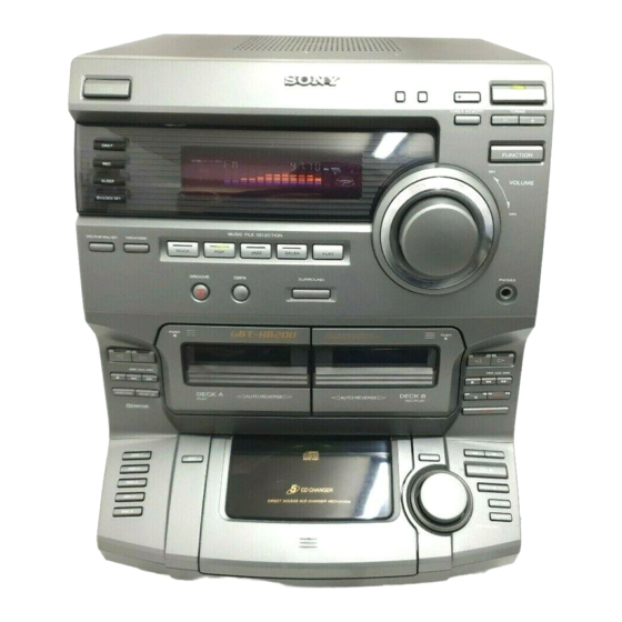
Sony HCD-DR3 Service Manual
Hide thumbs
Also See for HCD-DR3:
- Service manual (10 pages) ,
- Service manual (52 pages) ,
- Service manual (10 pages)
Table of Contents
Advertisement
Quick Links
HCD-DR3/DR330/XB200
SERVICE MANUAL
HCD-DR3/DR330/XB200 is the tuner, deck,
CD and amplifier section in LBT-DR3/
DR330/XB200.
Manufactured under license from Dolby Laboratories
Licensing Corporation.
"DOLBY" and the double-D symbol a are trademarks
of Dolby Laboratories Licensing Corporation.
Amplifier section
(LBT-XB200)
DIN power output (Rated)
70W + 70W
(6 Ω at 1 kHz DIN)
Continuous RMS power output (Reference)
80W + 80W
(6 Ω at 1 kHz, 10%
THD)
Music power output (Reference)
140W + 140W
(6 Ω at 1 kHz, 10%
THD)
(LBT-DR330/DR3)
The following measured at AC 110/220V, 60Hz ;
Continuous RMS power output (Reference)
85W + 85W
(6 Ω at 1 kHz, 10%
THD)
DIN power output (Rated)
70W + 70W
(6 Ω at 1 kHz, DIN)
The following measured at AC 120/240V, 60Hz ;
Continuous RMS power output (Reference)
100W + 100W
(6 Ω at 1 kHz, 10%
THD)
DIN power output (Rated)
80W + 80W
(6 Ω at 1 kHz, DIN)
Inputs
PHONO IN (phono jack):
sensitivity 3mV,
impedance 47 kΩ
MICROFILM
All manuals and user guides at all-guides.com
SECTION
SECTION
SPECIFICATIONS
SPECIFICATIONS
MD/VIDEO IN (phono jacks):
Outputs
PHONOS (stereo phono jacks):
MD/VIDEO OUT (phone jack):
SPEAKER:
CD player section
System
Laser
Laser output
Model Name Using Similar Mechanism
CD
Base Unit Type
Optical Pick-up Type
TAPE
Model Name Using Similar Mechanism
DECK
Tape Transport Mechanism Type
Wavelength
sensitivity 250mV,
Frequency response
impedance 47 kΩ
Signal-to-noise retio
Dynamic range
DIGITAL OUT
accepts headphones of 8 Ω
(Square optical connector jack, rear panel)
or more
Wavelength
Output Level
voltage 250mV,
Tape deck section
impedance 1 kΩ
accepts impedance of 6 to
Recording system
16 Ω
Frequency response (DOLBY NR OFF)
Compact disc and digital
audio system
Tuner section
Semiconductor laser
(λ = 780 nm)
FM stereo, FM/AM superheterodyne tuner
Emission
duration: continuous
FM tunr section
Max. 44.6µW*
Tuning range
*This output is the value
measured at a distance of
200 mm from the objective
lens surface on the Optical
Pock-up Block with 7 mm
aperture.
COMPACT Hi-Fi STEREO SYSTEM
AEP Model
UK Model
HCD-XB200
E Model
HCD-DR3/DR330
Australian Model
HCD-DR3
HCD-G2500
KSM-213ECM/C2NP
KSS-213E/C2N
NEW
CWL-44-RR
780 – 790 nm
20Hz – 20kHz (±0.5 dB)
More than 90 dB
More than 90 dB
600 nm
–18 dBm
4-track 2-channel stereo
60 – 13,000 Hz (±3 dB),
using a Sony TYPE I
cassette
87.5 – 108.0 MHz
(50 kHz step)
Continued on next page
Advertisement
Table of Contents

Related Manuals for Sony HCD-DR3


Summary of Contents for Sony HCD-DR3
- Page 1 AEP Model UK Model HCD-XB200 E Model HCD-DR3/DR330 Australian Model HCD-DR3 HCD-DR3/DR330/XB200 is the tuner, deck, CD and amplifier section in LBT-DR3/ DR330/XB200. Manufactured under license from Dolby Laboratories Model Name Using Similar Mechanism HCD-G2500 Licensing Corporation. Base Unit Type...
- Page 2 CLASS 1 LASER PRODUCT MARKING is located on the rear LIST ARE CRITICAL TO SAFE OPERATION. REPLACE THESE exterior. COMPONENTS WITH SONY PARTS WHOSE PART NUMBERS APPEAR AS SHOWN IN THIS MANUAL OR IN SUPPLEMENTS The following caution label is located inside the unit.
-
Page 3: Table Of Contents
All manuals and user guides at all-guides.com TABLE OF CONTENTS 1. GENERAL ·········································································· 4 2. DISASSEMBLY 2-1. Top Cover ··········································································· 5 2-2. Front Panel Assy ································································· 5 2-3. Main Section ······································································· 6 2-4. Main Board ········································································· 6 2-5. CD Mechanism Deck Section ············································ 7 2-6. -
Page 4: General
All manuals and user guides at all-guides.com SECTION 1 GENERAL %¢ %£ $• $ª %º %™ %¡ $∞ $¢ $§ $¶ !¡ $¡ $™ $£ !™ !£ #ª $º !¢ !∞ !§ #§ #¶ #• !¶ !• !ª #¢ #∞ #£... -
Page 5: Disassembly
All manuals and user guides at all-guides.com SECTION 2 DISASSEMBLY Note : Follow the disassembly procedure in the numerical order given. 2-1. TOP COVER 3 Top cover 1 Three screws 1 Three screws 2 Seven screws 2-2. FRONT PANEL ASSY 8 Board to board connector (CN602) 7 Screw... -
Page 6: Main Section
All manuals and user guides at all-guides.com 2-3. MAIN SECTION 1 Connector (CN301) 7 Main section 2 Screw 4 Three screws 6 Two screws 3 Photo Socket board 5 Two screws 2-4. MAIN BOARD 5 Rear panel 1 Four screws 8 Main board 2 Three screws 3 Four screws... -
Page 7: Cd Mechanism Deck Section
All manuals and user guides at all-guides.com 2-5. CD MECHANISM DECK SECTION 3 Four screws 4 CD mechanism deck section 2 Holder, wire 1 Two screws 2-6. TAPE MECHANISM DECK 1 Flexible flat cable 2 Six screws (to connector 16pin on tape mechanism deck) 3 Tape mechanism deck... -
Page 8: Cassette Doors
All manuals and user guides at all-guides.com 2-7. CASSETTE DOORS Cassette door (L) (Note: Four claws are used.) Cassette door (R) (Note: Four claws are used.) 2-8. CD CHASSIS ASSY 5 AMS knob !™ CD chassis assy 6 Nut 2 Connector (CN606) 7 Washer !¡... -
Page 9: Base Unit
All manuals and user guides at all-guides.com 2-9. BASE UNIT 2 Connector (CN01) 1 Connector (CN02) 5 Base unit 4 Boss 3 Yoke bracket 2-10. TURN TABLE Note: When the disc table is installed, adjust the positions of roller can and mark ” as shown in the figure, then set to the groove of disc table. -
Page 10: Mechanical Adjustments
All manuals and user guides at all-guides.com SECTION 3 SECTION 4 MECHANICAL ADJUSTMENTS ELECTRICAL ADJUSTMENTS Precaution DECK SECTION 0 dB=0.775V 1. Clean the following parts with a denatured alcohol-moistened Demagnetize the record/playback head with a head swab: demagnetizer. record/playback head pinch rollers Do not use a magnetized screwdriver for the adjustments. - Page 11 All manuals and user guides at all-guides.com Mode: Playback Tape Speed Adjustment (Deck A) Procedure: test tape Mode: Playback SPEAKER P-4-A100 terminal (JK703) (10kHz, –10dB) (L-CH) test tape oscilloscope WS-48B frequency counter (3kHz, 0dB) – SPEAKER SPEAKER terminal (JK703) terminal (JK703) (R-CH) Waveform of oscilloscope Adjust the SFR601 so that the frequency counter reads 3,000...
- Page 12 All manuals and user guides at all-guides.com TUNER SECTION 0 dB=1µV AM Tuning Voltage Adjustment DC voltmeter Main board – Procedure: Set the reception frequency of the unit to 530 kHz. Adjust L105 for 1.2 ± 0.05 V reading on the DC voltmeter. Set the reception frequency of the unit to 1,710 kHz.
- Page 13 All manuals and user guides at all-guides.com FM Tuned Level Adjustment FM RF SSG 75 Ω coaxial Carrier frequency : 98 MHz Modulation : AUDIO 1 kHz, 75 kHz FM ANTENNA terminal deviation (100%) (JK101) Output level : 28 dB (at 75 W open) Procedure: Supply a 28 dB 98 MHz signal from the ANTENNA terminal.
- Page 14 All manuals and user guides at all-guides.com CD SECTION Note: CD Block is basically constructed to operate without adjustment. Therefore, check each item in order given. Use YEDS-18 disc (3-702-101-01) unless otherwise indicated. Use an oscilloscope with more than 10MΩ impedance. Clean the object lens by an applicator with neutral detergent when the signal level is low than specified value with the following checks.
-
Page 15: Diagrams
All manuals and user guides at all-guides.com SECTION 5 DIAGRAMS • Waveform 5-1. CIRCUIT BOARDS LOCATION THIS NOTE IS COMMON FOR PRINTED WIRING BOARDS AND SCHEMATIC DIAGRAMS. MAIN BOARD (In addition to this necessary note is printed in each POWER (AMP) board IC103 @™... -
Page 16: Block Diagrams
All manuals and user guides at all-guides.com HCD-DR3/DR330/XB200 5-2. BLOCK DIAGRAM MAIN SECTION CD L JK201 SECTION (PAGE 17) MD/VIDEO OUT JK201 IC203 R CH IC202 PHONO R CH Q209 Q207 Q210 MUTE MD/VIDEO Q201 R CH SELECTOR EQ AMP... -
Page 17: Tuner/Cd Section
All manuals and user guides at all-guides.com HCD-DR3/DR330/XB2 TUNER/CD SECTION FM/AM MPX FM FRONT END IC102 FE101 Q101 CF101 CF102 TU L 10.7MHz RF IF 10.7MHz FM IF AM/FM MUTE DECODER 75Ω IF BUFF R CH JK101 ANTENNA Q117 CF104... -
Page 18: Printed Wiring Board
All manuals and user guides at all-guides.com HCD-DR3/DR330/XB200 5-3. PRINTED WIRING BOARD MAIN SECTION • Refer to page 15 for Circuit Boards Location. MAIN BOARD • Semiconductor Location Ref. No. Location Ref. No. Location DR3/DR330 D104 C121 R118 D111 C122... -
Page 19: Main (1/3) Section
All manuals and user guides at all-guides.com HCD-DR3/DR330/XB2 5-4. SCHEMATIC DIAGRAM MAIN (1/3) SECTION • Refer to page 15 for Waveform. • Refer to page 31 for IC Block Diagrams. -
Page 20: Main (2/3) Section
All manuals and user guides at all-guides.com HCD-DR3/DR330/XB200 5-5. SCHEMATIC DIAGRAM MAIN (2/3) SECTION • Refer to page 15 for Waveform. • Refer to page 18 for Printed Wiring Board. -
Page 21: Main (3/3) Section
All manuals and user guides at all-guides.com HCD-DR3/DR330/XB2 5-6. SCHEMATIC DIAGRAM MAIN (3/3) SECTION • Refer to page 18 for Printed Wiring Board. • Refer to page 31 for IC Block Diagrams. -
Page 22: Amp Section
All manuals and user guides at all-guides.com HCD-DR3/DR330/XB200 5-7. PRINTED WIRING BOARD AMP SECTION • Refer to page 15 for Circuit Boards Location. • Semiconductor Location Ref. No. Location JK703 JK701 EXCEPT E,SP,AR SPEAKER D701 PHONES POWER SUPPLY BOARD D702... -
Page 23: Amp Section
All manuals and user guides at all-guides.com HCD-DR3/DR330/XB2 5-8. SCHEMATIC DIAGRAM AMP SECTION • Refer to page 32 for IC Block Diagram. EXCEPT E,SP,AR MODELS AUS, XB200:T2.5AL 250V MX:5A 250V E,SP,AR MODELS JK703 The components identified by mark ! or dotte line with mark ! are critical for safety. -
Page 24: Cd Decoder Section
All manuals and user guides at all-guides.com HCD-DR3/DR330/XB200 5-9. PRINTED WIRING BOARD CD DECORD SECTION • Refer to page 15 for Circuit Boards Location. • Semiconductor Location Ref. No. Location CONNECTOR BOARD D-11 CD DECODER BOARD IC01 IC02 IC03 IC04... -
Page 25: Schematic Diagram Cd Decoder Section
All manuals and user guides at all-guides.com HCD-DR3/DR330/XB2 5-10. SCHEMATIC DIAGRAM CD DECORD SECTION • Refer to page 15 for Waveforms. The components identified by mark ! or dott line with mark ! are critical for safety. Replace only with part number specified. -
Page 26: Printed Wiring Board
All manuals and user guides at all-guides.com HCD-DR3/DR330/XB200 5-11. PRINTED WIRING BOARD FRONT SECTION • Refer to page 15 for Circuit Boards Location. • Semiconductor Location Ref. No. Location FRONT BOARD D601 C-11 REM BOARD LED602 DR3:SP D602 C-11 DR3:E,AUS... -
Page 27: Schematic Diagram Front (1/2) Section
All manuals and user guides at all-guides.com HCD-DR3/DR330/XB2 5-12. SCHEMATIC DIAGRAM FRONT (1/2) SECTION • Refer to page 15 for Waveform. • Refer to page 29 for IC Pin Function Description. • Refer to page 32 for IC Block Diagrams. -
Page 28: Schematic Diagram Front (2/2) Section
All manuals and user guides at all-guides.com HCD-DR3/DR330/XB200 5-13. SCHEMATIC DIAGRAM FRONT (2/2) SECTION • Refer to page 26 for Printed Wiring Board. -
Page 29: Ic Pin Function Description
All manuals and user guides at all-guides.com 5-14. IC PIN FUNCTION DESCRIPTION IC601 LC866540A-5K40 SYSTEM CONTROL (FRONT board) Pin No. Pin Name Description POWER OUT Power on/off output S.MUT System mute output (ON at H) TU.MUT OUT Tuner mute output (ON at H) SURROUND OUT Surround output (ON at H) DBFB HI/LOW... - Page 30 All manuals and user guides at all-guides.com Pin No. Pin Name Description P4 S3 FLD segment output 4 P5 S4 FLD segment output 5 P6 S5 FLD segment output 6 P7 S6 FLD segment output 7 P8 S7 FLD segment output 8 P9 S8 FLD segment output 9 P10 S9...
-
Page 31: Ic Block Diagrams
All manuals and user guides at all-guides.com 5-15. IC BLOCK DIAGRAMS MAIN BOARD IC103 LC72131M PHASE DETECTOR CHARGE PUMP POWER REFERENCE UNLOCK DIVIDER DETECTOR RESET SWALLOW COUNTER 1/16, 1/17 4BITS 12BITS PROGRAMMABLE DRIVER UNIVERSAL DATA SHIFT REGISTER LATCH INTERFACE COUNTER 2 3 4 5 6 7 8 9 IC202... - Page 32 All manuals and user guides at all-guides.com FRONT BOARD IC602 BU2092F-E2 IC603 BU2114F 16 15 14 13 12 11 12 BIT CONTROL SHIFT SHIFT CIRCUIT REGISTER REGISTER OUTPUT LATCH 12 BIT LATCH BUFFER STORAGE (OPEN DRAIN) REGISTER SOUT ENABLE 5 6 7 8 9 IC606 SN74HC161 RIPPLE...
-
Page 33: Exploded Views
All manuals and user guides at all-guides.com SECTION 6 EXPLODED VIEWS NOTE: • The mechanical parts with no reference number • Abbreviation The components identified by mark ! or in the exploded views are not supplied. SP : Singapore model dotted line with mark ! are critical for safety. -
Page 34: Cd Door Section
All manuals and user guides at all-guides.com 6-2. CD DOOR SECTION not supplied Ref. No. Part No. Description Remarks Ref. No. Part No. Description Remarks 4-221-007-01 BUTTON, CD PLAY(DR3,XB200) 4-221-005-01 BUTTON, CD EDIT(DR3,XB200) 4-222-126-01 BUTTON, CD PLAY(DR330) 4-222-124-01 BUTTON, CD EDIT(DR330) 4-221-008-01 LENS, CD PLAY BUTTON 4-220-995-01 PANEL, CD FRONT(DR3,XB200) 4-221-006-01 BUTTON, CD SKIP(DR3,XB200) -
Page 35: Panel Section
All manuals and user guides at all-guides.com 6-3. PANEL SECTION Not supplied Not supplied supplied Ref. No. Part No. Description Remarks Ref. No. Part No. Description Remarks 4-221-028-01 BUTTON (R), CASS(DR3,XB200) 4-221-023-01 BUTTON, CLOCK 4-222-130-01 BUTTON (R), CASS(DR330) 4-220-987-01 PLATE, DISPLAY 4-221-034-01 LENS (A), CASS BUTTON (R) 1-772-164-11 DECK, MECH 4-221-035-01 LENS (B), CASS BUTTON (R) -
Page 36: Main Section
All manuals and user guides at all-guides.com 6-4. MAIN SECTION not supplied not supplied E,MX MODEL SP MODEL SP,AEP,EE, CIS MODEL UK MODEL AUS, AR MODEL not supplied CD section T001 not supplied not supplied not supplied Ref. No. Part No. Description Remarks Ref. -
Page 37: Cd Mechanism Section
All manuals and user guides at all-guides.com 6-5. CD MECHANISM SECTION not supplied not supplied 207 208 not supplied Base unit block Ref. No. Part No. Description Remarks Ref. No. Part No. Description Remarks 4-987-976-01 SCREW,STEP 1-675-422-11 MOTOR BOARD 4-944-490-01 BELT(TIMING) 4-223-441-01 INDICATOR 4-223-449-01 GEAR (MID) 1-675-423-11 DISC NO BOARD... -
Page 38: Base Unit Section (Ksm-213Ecm)
All manuals and user guides at all-guides.com 6-6. BASE UNIT SECTION (KSM-213ECM) not supplied not supplied M102 M101 Ref. No. Part No. Description Remarks Ref. No. Part No. Description Remarks 4-223-456-01 DAMPER(GR) 2-626-907-01 GEAR (A)(S) 4-223-457-01 DAMPER(RD) 4-992-164-01 BASE, KSM MECHANICAL 3-319-501-51 SCREW(+ PTPWH) (2.6 ×... -
Page 39: Electrical Parts List
All manuals and user guides at all-guides.com AC SWITCH SECTION 7 ELECTRICAL PARTS LIST CD DECORD NOTE: • Due to standardization, replacements in the • RESISTORS • SEMICONDUCTORS parts list may be different from the parts All resistors are in ohms. In each case, u: µ, for example: specified in the diagrams or the components METAL: metal-film resistor... - Page 40 All manuals and user guides at all-guides.com CD DECORD Ref. No. Part No. Description Remarks Ref. No. Part No. Description Remarks 1-126-963-11 ELECT 4.7uF 1-249-439-11 CARBON 1/4W 1-126-963-11 ELECT 4.7uF 1-247-879-11 CARBON 100K 1/4W 1-162-294-31 CERAMIC 0.001uF 1-247-883-00 CARBON 150K 1/4W 1-162-294-31 CERAMIC 0.001uF...
- Page 41 All manuals and user guides at all-guides.com CD DECORD CD KEY CD SENSOR CD SW CONNECTOR DISC NO FRONT Ref. No. Part No. Description Remarks Ref. No. Part No. Description Remarks 1-249-417-11 CARBON 1/4W F 1-675-423-11 DISC NO BOARD 1-249-417-11 CARBON 1/4W F ************* 1-249-417-11 CARBON...
- Page 42 All manuals and user guides at all-guides.com FRONT Ref. No. Part No. Description Remarks Ref. No. Part No. Description Remarks C645 1-126-957-11 ELECT 0.22uF < IC > C646 1-126-957-11 ELECT 0.22uF C647 1-162-306-11 CERAMIC 0.01uF IC601 8-759-595-06 IC LC866540A-5K40 C648 1-126-957-11 ELECT 0.22uF IC602...
- Page 43 All manuals and user guides at all-guides.com FRONT Ref. No. Part No. Description Remarks Ref. No. Part No. Description Remarks R616 1-247-855-11 CARBON 1/4W R703 1-249-410-11 CARBON 1/4W F R617 1-247-807-11 CARBON 1/4W R704 1-247-855-11 CARBON 1/4W R618 1-247-807-11 CARBON 1/4W R705 1-249-417-11 CARBON...
- Page 44 All manuals and user guides at all-guides.com FRONT MAIN Ref. No. Part No. Description Remarks Ref. No. Part No. Description Remarks S606 1-762-875-11 SWITCH, KEYBOARD (TAPE B, ”) < RESISTOR > 1-762-875-11 SWITCH, KEYBOARD (TAPE B, “) S607 S608 1-762-875-11 SWITCH, KEYBOARD (TAPE B, p) R448 1-249-409-11 CARBON 1/4W F...
- Page 45 All manuals and user guides at all-guides.com MAIN Ref. No. Part No. Description Remarks Ref. No. Part No. Description Remarks C162 1-161-494-00 CERAMIC 0.022uF C236 1-126-961-11 ELECT 2.2uF C163 1-161-494-00 CERAMIC 0.022uF C237 1-109-889-11 ELECT C164 1-126-962-11 ELECT 3.3uF C238 1-126-933-11 ELECT 100uF C165...
- Page 46 All manuals and user guides at all-guides.com MAIN Ref. No. Part No. Description Remarks Ref. No. Part No. Description Remarks C345 1-109-953-11 ELECT 2.2uF C862 1-126-964-11 ELECT 10uF C346 1-137-401-11 FILM 0.22uF 100V C863 1-126-964-11 ELECT 10uF C347 1-162-294-31 CERAMIC 0.001uF C864 1-126-964-11 ELECT...
- Page 47 All manuals and user guides at all-guides.com MAIN Ref. No. Part No. Description Remarks Ref. No. Part No. Description Remarks D303 8-719-010-73 DIODE UZ-12BSA Q201 8-729-194-57 TRANSISTOR 2SC945TP-P D304 8-719-010-45 DIODE UZ-6.2BSA Q202 8-729-194-57 TRANSISTOR 2SC945TP-P D305 8-719-911-19 DIODE 1SS133 Q203 8-729-194-57 TRANSISTOR 2SC945TP-P D306...
- Page 48 All manuals and user guides at all-guides.com MAIN Ref. No. Part No. Description Remarks Ref. No. Part No. Description Remarks R123 1-249-428-11 CARBON 8.2K 1/4W F R232 1-247-839-11 CARBON 2.2K 1/4W R124 1-247-843-11 CARBON 3.3K 1/4W R233 1-249-427-11 CARBON 6.8K 1/4W F R126 1-249-417-11 CARBON...
- Page 49 All manuals and user guides at all-guides.com MAIN Ref. No. Part No. Description Remarks Ref. No. Part No. Description Remarks R332 1-247-855-11 CARBON 1/4W R845 1-247-863-11 CARBON 1/4W R333 1-247-871-11 CARBON 1/4W R846 1-247-863-11 CARBON 1/4W R334 1-247-871-11 CARBON 1/4W R847 1-249-417-11 CARBON 1/4W F...
- Page 50 All manuals and user guides at all-guides.com MAIN MOTOR MOTOR (6P) (S) POWER SUPPLY POWER (AMP) Ref. No. Part No. Description Remarks Ref. No. Part No. Description Remarks R916 1-247-899-11 CARBON 680K 1/4W 1-674-638-11 POWER SUPPLY BOARD R917 1-247-885-00 CARBON 180K 1/4W *******************...
- Page 51 All manuals and user guides at all-guides.com POWER (AMP) Ref. No. Part No. Description Remarks Ref. No. Part No. Description Remarks C748 1-161-494-00 CERAMIC 0.022uF < TRANSISTOR > C749 1-161-494-00 CERAMIC 0.022uF C750 1-161-494-00 CERAMIC 0.022uF Q702 8-729-188-23 TRANSISTOR 2SD882-P C751 1-126-943-11 ELECT 2200uF...
- Page 52 All manuals and user guides at all-guides.com HCD-DR3/DR330/XB200 POWER (AMP) PHOTO SOCKET Ref. No. Part No. Description Remarks Ref. No. Part No. Description Remarks R738 1-247-784-00 CARBON 1/4W 1-674-642-11 TR BOARD (XB200) ******** R739 1-215-857-11 METAL OXIDE R740 1-216-450-00 METAL OXIDE <...
Need help?
Do you have a question about the HCD-DR3 and is the answer not in the manual?
Questions and answers