Table of Contents
Advertisement
Advertisement
Table of Contents

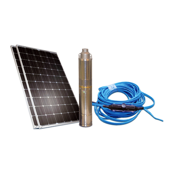
Summary of Contents for DAYLIFF SUNFLO-S 150
- Page 1 SOLAR PUMPING SYSTEMS Installation & Operating Manual...
- Page 3 INDEX SPECIFICATIONS 1.1 Pump 1.2 Power Outputs 1.3 Pump Data 2. EQUIPMENT INSTALLATION 2.1 Module Positioning 2.2 Pump Installation 2.3 Electrical Wiring 2.4 Low Water Level Protection 2.5 High Water Level Tank Sensor 3. BATTERY SYSTEMS 4. SYSTEM OPERATIONS 4.1 Pump 4.2 Controller 4.2.1 Suno-S 4.2.2 Suno-A...
-
Page 4: Specifications
Congratulations on selecting a Dayliff SunFlo Solar Pumping System. They are manufactured to the highest standards and if installed and operated correctly will give many years of efcient and trouble free service. Careful reading of this Installation Manual is therefore important, though should there be any queries they should be referred to the equipment supplier. -
Page 5: Equipment Installation
Voltage Voltage Rating length, Voltage Modules Performance Size Watts 2.5mm (VoC) 1m /day at 30m SUNFLO-S 150 1x200W ½” ≤50 3m /day at 60m 2x200W SUNFLO-S 300 2m /day at 30m SUNFLO-A 150H 1x200W ≥20 ≤60 3m /day at 50m 2x200W ¾”... -
Page 6: Pump Installation
Pumps can be installed in wells or boreholes and should be provided with fittings as indicated in Fig1. Piping options are Dayliff PVC for deep wells, galvanized steel or HDPE. The latter is recommended for shallower wells due to simplified lowering. When installing the pump ensure to fit the safety rope which can be used to lower the pump down. -
Page 7: Electrical Wiring
Ball Check Valve Valve Outlet Cable Pressure Gauge Rope Allowed Min 10 Allowed Fig. 1 Pump Installation Arrangement Fig. 2 Pump Axis Limits 2.3 ELECTRICAL WIRING Cover modules during connection to avoid electric shocks, Connections should be done in the early morning or late afternoon when irradiation is low. - Page 8 MCB overload protection. All wiring connections should be made with the isolator 'off'. SunFlo-S System Layout PV MODULES Outlet Charge DC Isolator Batteries Controllers SunFlo-S 150 - 1 PV MODULE SunFlo-S 300 - 2 PV MODULES Fig.3 SunFlo-A System Layout PV MODULES OUTLET DC ISOLATOR MODULE CONNECTIONS...
- Page 9 SunFlo-B System Layout PV MODULES OUTLET MPPT PUMP CONTROLLER DC ISOLATOR SunFlo-B 120H - 1 PV MODULE SunFlo-B 500C - 4 PV MODULES SunFlo-B 1000C - 8 PV MODULES MODULES CONNECTIONS Fig.5 SunFlo-B Controller Connection Motor Battery Tank Well Solar COM1 COM2 Water Pipe...
-
Page 10: Battery Systems
When provided, separate Controllers should be located adjacent to the Isolator and care taken to ensure correct connections to the terminal block. The controller isolator must be 'off' during connections. 2.4 LOW WATER LEVEL PROTECTION Water level sensors are unnecessary when there is no risk of draw down to the pump. -
Page 11: System Operations
Pump Battery Capacity Series Connection Pump Power, Voltage Watts 2hrs 5hrs 2No. 18Ah/12V 2No. 35Ah/12V 2No. 35Ah/12V 2No. 100Ah/12V 4No. 35Ah/12V 4No. 100Ah/12V 4. SYSTEM OPERATIONS 4.1 PUMP Generally pump operation is fully automatic with pump flow starting with low output at around 8am building to a peak at mid-day and stopping around 5pm. -
Page 12: Indicator Lights
4.2.2 SunFlo-A Pumps are controlled by an internal motor controller with no external monitoring or adjustment provisions. However, pumps must be connected through the PV Isolator that also provides over-current protection. 4.2.3 SunFlo-B All SunFlo-B pumps are provided with an advanced MPPT controller that enhances pump performance by up to 25%. -
Page 13: Time Delay
Controls Time delay Speed button Solar battery diverter switch Speed Control – Modulates the pump speed by regulating pump efficiency. Turn fully clockwise for 100% efficiency and fully anti-clockwise for minimum 30% efficiency. This function allows PV module output to be shared between the pump and battery charging according to the set proportion and for reduced pump output in the event of over- pumping. -
Page 14: Troubleshooting
5. TROUBLE SHOOTING PROBLEM POSSIBLE CAUSE SOLUTION Low voltage Check solar irradiation Ensure the pump is installed below No water at pump level the lowest water level Pump operates with Correct installation to the recommended Pump located too deep no flow or reduced level flow Clogged filter screen... -
Page 15: Terms Of Warranty
6. TERMS OF WARRANTY i) General Liability In lieu of any warranty, condition or liability implied by law, the liability of Dayliff in Ÿ respect of any defect or failure of equipment supplied is limited to making good by replacement or repair (at the Company’s discretion) defects which under proper use appear therein and arise solely from faulty design, materials or workmanship within a specified period. - Page 16 www.davisandshirtliff.com INS420A-05/19...


Need help?
Do you have a question about the SUNFLO-S 150 and is the answer not in the manual?
Questions and answers