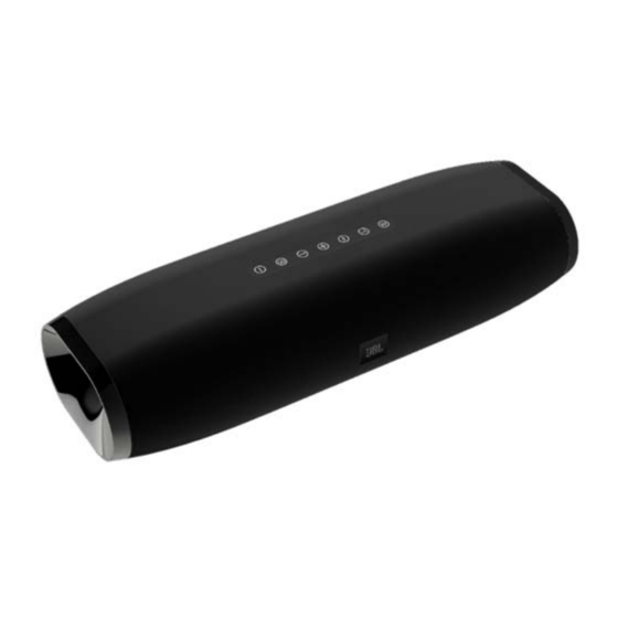
JBL BOOST TV Service Manual
Hide thumbs
Also See for BOOST TV:
- Quick start manual (17 pages) ,
- Owner's manual (5 pages) ,
- Handleiding (5 pages)

Related Manuals for JBL BOOST TV


Summary of Contents for JBL BOOST TV
-
Page 1: Table Of Contents
Service Manual BOOST TV The easiest way to make smaller television sound better. CONTENTS Schematics Diagram Safety Information Layout Diagram Technical Specifications Mechanical Exploded View Dismantling Instruction Packaging Exploded View Set Block Diagram Spare Parts List Set Wiring Diagram Revision List Ver.1.4 06/2016... -
Page 2: Safety Information
Important Safety Instructions 1. Read these instructions. CAUTION 2. Keep these instructions. 3. Heed all warnings. RISK OF ELECTRIC SHOCK. DO NOT OPEN. 4. Follow all instructions. 5. Do not use this apparatus near water. 6. Clean only with a dry cloth. 7. - Page 3 Some semiconductor (solid state) devices can be damaged easily by static electricity. Such components commonly are called Electrostatically Sensitive (ES) Devices. Examples of typical ES devices are integrated circuits and some field effect transistors and semiconductor "chip" components. The following techniques should be used to help reduce the incidence of component damage caused by static electricity. 1.
- Page 4 SAFETY PRECAUTIONS The following check should be performed for the continued protection of the customer and service technician. LEAKAGE CURRENT CHECK Measure leakage current to a known earth ground (water pipe, conduit, etc.) by connecting a leakage current tester between the earth ground and all exposed metal parts of the appliance (input/output terminals, screwheads, metal overlays, control shaft, etc.).
-
Page 5: Technical Specifications
Technical Specifications Audio Amplifier Section Description Specification Rated Output Power at 1% THD+N 15W x2 (4 ohm load) Measure at 1KHz System gain Analog : 30dB +/- 1dB Digital : 30dB +/- 1dB Measure at 1KHz Input Sensitivity Analog : 250mV +/- 1dB Digital : -18dBFS +/- 1dB Measure at 1KHz Input Overload... -
Page 6: Dismantling Instruction
DISMANTLING INSTRUCTIONS 3.DismantleGrille1andGrille2 1.RipofftheRubberButtonandRubber 2.DisassembleButton BracketandFeet Pad. Bracket Bracket. 4 Separate Front and Rear Housing 4.SeparateFrontandRearHousing. 5.Pullupthecab blesfromMainBoard 6.Loosen6pcsscrews。... - Page 7 9.Loosen4pcsscrewstotaketheAUX 7.Loosen8screwsandtakeoutdriver 8.DisassembletheKeyb oardandreceiver.Take Board off Boardoff. the Key Board off by scre theKeyBoardoffbyscre ew driver Pay more ewdriver.Paymore brackets brackets attentiontoyellowglueo oncablethroughthehole. 10 Loosen 9 pcs screws to disassemble Port tube 10.Loosen9pcsscrewstodisassemblePorttube. 11 Loosen 5pcs screws to disassemble the 11.Loosen5pcsscrewstodisassemblethe LeftorRightBassPort.
-
Page 8: Set Block Diagram
SET BLOCK DIAGRAM BLUETOOTH BM880 MICRO USB FOR UPGRADE SPDIF LCH 15W CODOC 4 OHM ANALOG AUX_IN TPA3118 NJM4580*2 SPDIF CS42528 AMPLIFIER OPTICAL IN RCH 15W MCLK 4 OHM I2S x1 DSP(Dobly digital) XTAL 12.288MHz MCLK 16M FLASH CS48L11 16K BIT EEPROM XTAL 4MHz 24C16 AUX_IN_DETECT... -
Page 9: Set Wiring Diagram
SET WIRING DIAGRAM... -
Page 10: Schematics Diagram
SCHEMATIC DIAGRAM - MAIN BOARD (MCU PART) 3PIN SOCKET BD471SN BD471SN C178 C179 [2,3] C182 C181 MCU_3.3V 24C16 R108 R112 KH25L1606E R205 R206 100K R204 POWER_DET PRODUCT_ID1 FLASH_CS PRODUCT_ID0 FLASH_MISO HOLD [2,3] [1,2,3] R105 R121 R190 A3.3V FLASH_CLK SCL_BUS [1,2] R189 OPTICAL_IN R207... - Page 11 SCHEMATIC DIAGRAM - MAIN BOARD (DSP+CODEC PART) CODEC_DAI_D1 DSP_DAO_D1 DSP_DAO_D2 DSP_CLK [1,2,3] DSP_DAO_D3 CODEC_DAI_LRCK [1,2,3] SW_DAI_DI CODEC_DAI_SCLK [1,2,3] DSP_DAO_D3 CODEC_DAI_LRCK BD471SN [2,3] [1,2,3] P3.3V CODEC_DAI_SCLK CS48L11 DSP_CLK L18 BD471SN BD471SN P1.2V C109 [2,3] DSP_DAO_D1 P3.3V C108 MCLK [1,2,3] CODEC_DAI_SCLK VPLL DBDA C107 [1,2,3]...
- Page 12 SCHEMATIC DIAGRAM - MAIN BOARD (BT+AMP PART) IN4148 ANT SOCKET [1,2] C118 ANT1 C149 470P C163 C100 R103 C119 10.5K ADC_AINL+ C157 C158 AUX_LIN [1,3] U11-B R116 R167 C8550 NJM4580 100K C110 C130 470P [2,3] R155 CODEC_DAI_SCLK BAT54C NJM4580 C164 R104 CODEC_MUTE U11-A...
- Page 13 SCHEMATIC DIAGRAM - KEY BOARD, AUX BOARD, IR BOARD 18PIN FPC SOCKET CN10 2.2K R252 R251 10K1% 10K1% 10K1% R227 R243 R221 3PIN WIRE CN11 KLED_STANDBY SURROUND VOL- VOL+ KLED_POWON 7.5K1% 7.5K1% 7.5K1% C219 C218 R222 R235 R223 KLED_VOL+ 3.3V KLED_VOL- BLUETOOTH POWER...
-
Page 14: Layout Diagram
LAYOUT DIAGRAM - MAIN BOARD... - Page 15 LAYOUT DIAGRAM - KEY BOARD...
- Page 16 LAYOUT DIAGRAM - AUX BOARD LAYOUT DIAGRAM - IR BOARD...
-
Page 17: Mechanical Exploded View
SET MECHANICAL EXPLODED VIEW... -
Page 18: Packaging Exploded View
PACKAGING EXPLODED VIEW EPE bag Manual EPE bag Accessory box Remote Control 231110497009 Beauty box Beauty box 462110497009 462110497009 EPE bag Accessory box Carton box Carton box 462310497009 462310497019 462310497019... -
Page 19: Spare Parts List
IC AS2930-3.3V SOT23-5 BOOST TV 403902570929 IC AS2930-1.2V SOT23-5 BOOST TV 403903600909 IC 74LVC2G04GW NXP Dual inverter 6 leads SOT363 BOOST TV 403903600919 IC 74LVC1G3157GV NXP 2-channel analog SOT457 BOOST TV 403903880209 IC 24C16-WMN6TP EEPROM 16Kbit Serial I2C SOP-8 BOOST TV... - Page 20 416900010129 DC Jack D4 BOOST TV 416900960109 USB Jack Micro USB UR1-075AB50-NAZP BOOST TV ESD2‐ESD3 ESD5 403903511009 ESD ESDA0603-05 5.5V 5pF +30-20 0603 BOOST TV ESD7 ESD8 416010120229 FPC Jack 10PIN*1 P=0.5MM H2mm BOOST TV 461121110079 2P Cable L=110MM W2.54MM BOOST TV...
- Page 21 40+41 420202030129 RUBBER FOOT BOOST TV WHT 420202020119 RUBBER BUTTON BOOST TV WHT 461011520129 POWER CORD EU L1.5M BOOST TV WHT 461011521119 POWER CORD UK L1.5M BOOST TV WHT 461011521139 POWER CORD CN L1.5M BOOST TV WHT 461011521129 POWER CORD US L1.5M BOOST TV WHT 461011521149 POWER CORD JP L1.5M BOOST TV WHT...
-
Page 22: Revision List
Revision List V1.0 2015-09 Initial release V1.1 2015-10 Change the product name to Boost TV from TV Boost. V1.2 2015-12 Update 4 PCB Ass'y P/Ns on Page 19-20. V1.3 2016-04 Key Board P/N changed from 993104860409.to 993104860429. V1.4 2016-06 Spare Parts list of white cosmetics version added on Page 21.
Need help?
Do you have a question about the BOOST TV and is the answer not in the manual?
Questions and answers