Table of Contents
Advertisement
Quick Links
Advertisement
Table of Contents

Related Manuals for Body Sculpture BE-5925


Summary of Contents for Body Sculpture BE-5925
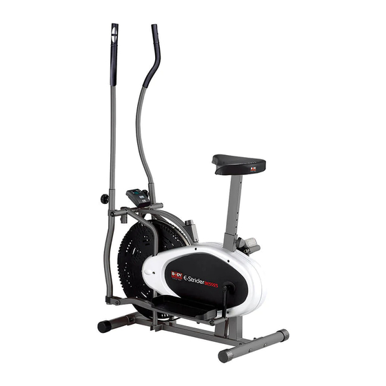
- Page 1 BE-5925 AERO ELLIPTICAL & BIKE www.body--sculpture.com...
- Page 2 ………………… Important Safe ty Information ………………..Exploded-View Assembly Drawing ……….………………………………………… Parts List … Assembly Instruction …………………………………… … ….………………………………… Tension Adjustment … ….……………………………… Exercise Instructions … ……..……………………………… Exercise Computer … ……..……………………………… Trouble Shooting …...
- Page 3 Please keep this manual in a safe place for reference. 1. It is important to read this entire manual before assembling and using the equipment. Safe and effective use can only be achieved if the equipment is assembled, maintained and used properly.
- Page 5 PART LIST PART PART DESCRIPTION DESCRIPTION Main Frame D Shape Washer (Ø28x5) Rear Stabilizer Spindle bar End Cap Pedal Key head Bolt M8*60 Bolt (M10*50) Domed Nut Crank (Right & Left) Curved Washer Right Handlebar Front Stabilizer Left Handlebar Transportation Wheel Locking knob Lower Handle bar (Right) Foam Grip...
- Page 6 No.28 Locking Knob No.19 Hinge Screw No.5 Domed Nut (M8) No.17 Nut (1/2“) No.15 Pedal Hinge Bolt No.4 Key head Bolt (M8*60) No.13 (M10) No.24 Bolt (M10*50) No.18 Spring Washer No.22 Spindle Bar Attached the Front and Rear Stabilizers (pt.7 & pt.2) with Four Carriage Bolts (pts.4), Washers (pts.6) and Domed Nuts (pts.5).
- Page 7 Insert the Spindle Bar (pt.22) through the Right Lower Handlebar (Pt.9)and through the main frame, and then, through the Left Handlebar (Pt.10). Put a D shape washer and a Spring Washer (Pts.20 &21) on either side of the spindle bar and tighten up both ends using the Hinge Screws (Pt.19) Then insert a Pedal Hinge Bolt (Pt.15R) and a Undee Washer (Pt.14) through the Pedal Post (Pt.11 for the right side, Pt.12 for the left), put a Spring Washer (Pt.18) on the bolt, then pass it through the Crank (Pt.25), and secure the bolt with an M12 Nut (Pt.17R).
- Page 8 Slide the computer (pt.32) onto the computer holder (pt.33), then connect the computer wire (pt. 31) and upper & lower pulse wire(42,43). See Fig.5. Fix the seat(36) onto seat post(38) with 3sets of Washer (Ø8) (39), Nylock Nut (M8) (40) Slide seat post (38), fix it with adjusting knob(37)
- Page 9 The assembly of your strider is now complete. When you try it for the first time, you should adjust the tension to the correct level before you begin a full workout. For minute tension adjustment, simply use the tension adjustment knob (pt.34) found at the top center. The tension level can be changed, using this adjustment knob to vary intensity of workout as you exercise.
-
Page 10: Exercise Instructions
Using your ELLIPTICAL STRIDER will provide you with several benefits. It will improve your physical fitness, tone your muscles and, in conjunction with a calorie-controlled diet, help you lose weight. 1.The Warm-Up Phase This stage helps get the blood flowing around the body and the muscles working properly. It will also reduce the risk of cramp and muscle injury. -
Page 11: Muscle Toning
3. The Cool-Down Phase This stage is to let your Cardio-vascular System and muscles wind down. This is a repeat of the warm up exercise e.g. reduce your tempo, continue for approximately 5 minutes. The stretching exercises should now be repeated, again remembering not to force or jerk your muscles into the stretch. As you get fitter you may need to train longer and harder. -
Page 12: Exercise Computer
EXERCISE COMPUTER FUNCTION BUTTON MODE PRESS TO SELECT FUNCTION DISPLAY, AND HOLD ON PRESSING FOR 4 SECONDS TO HAVE ALL FUNCTION VALUES TOTAL RESET. (THERE IS NO SINGLE FUNCTION RESET AVAILABLE.) FUNCTIONS SCAN AUTOMATICALLY SCANS THROUGH EACH FUNCTION EVERY 6 SECONDS. TIME DISPLAYS THE ACCUMULATED TIME UP TO 99:59 DURING EXERCISING. - Page 14 COPYRIGHT ©2005 BY BODY SCULPTURE INTERNATIONAL EUROPE LTD ALL RIGHTS RESERVED.UNAUTHORIZED DUPLICATION IS A VIOLATION OF LAW.
Need help?
Do you have a question about the BE-5925 and is the answer not in the manual?
Questions and answers