Subscribe to Our Youtube Channel
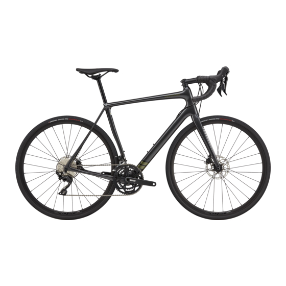
Summary of Contents for Cannondale Synapse HM
- Page 1 S Y N A P S E Read this supplement and your Cannondale Bicycle Owner’s Manual. Both contain important safety information. Keep both for future reference.
- Page 2 SYNAPSE - OWNERS MANUAL SUPPLEMENT SYNAPSE - OWNERS MANUAL SUPPLEMENT 134911 Rev 1. 134911 Rev 1.
- Page 3 ENGLISH ENGLISH CONTENTS Cannondale Supplements This manual is a “supplement” to your Cannondale Safety Information ......2-4 Bicycle Owner’s Manual. This supplement provides additional and important Technical Information ....... 5-15 model specific safety, maintenance, and technical information. It may be one of several important Replacement Parts........
- Page 4 “carbon fiber. ” Inspect frame carefully for damage (See PART II, All riders must understand a fundamental reality Section D. Inspect For Safety in your Cannondale of composites. Composite materials constructed Bicycle Owner’s Manual. )
- Page 5 ENGLISH Disc Brake on Road Bikes Tightening Torques Correct tightening torque for the fasteners (bolts, screws, nuts) on your bicycle is very important to your safety. Correct tightening torque for the fasteners is also important for the durability and performance of Relative to conventional rim brakes, disc brakes are your bicycle.
- Page 6 If you choose more lightweight components, you must inspect This kind of damage is not covered by the Cannondale Limited Warranty. them more frequently. If you are a heavier rider or have a rough, abusive or “go for it”...
- Page 7 ENGLISH TECHNICAL INFORMATION Frame Specification FRAME Synapse HM, Synapse Carbon HEAD TUBE See, “Headset Bearings” BOTTOM BRACKET BB30A 73mm FRONT DERAILLEUR braze-on / 1X SEAT POST DIA 25.4 mm MINIMUM SEAT POST INSERT 65 mm BRAKES Flat Mount REAR AXLE 142 x 12mm.
- Page 8 SYNAPSE - OWNERS MANUAL SUPPLEMENT Bottom Bracket – BB30A 73mm QC616/ KB6180/ KP249/BLK CK3588U00OS The small hole in the cable guide cover is to allow any accumulated water inside the BB30A frame to drain out. “asymmetric” Check to make sure it remains open. 73mm (5mm) 39mm...
- Page 9 KT011/. shell and is not recommended. Damage caused by improper installation/ To install bearings, use a headset press and Cannondale tool KT010/ . Clean inside of shell apply a high-quality removal is not covered under your warranty. bicycle bearing grease to the inside surface. Press bearing one at a time.
- Page 10 SYNAPSE - OWNERS MANUAL SUPPLEMENT Geometry Seat Tube Length Top Tube Horizontal Top Tube Actual Head Tube Angle Seat Tube Angle 75.0 Standover Head Tube Length Wheelbase Front Center Chain Stay Length Bottom Bracket Drop Bottom Bracket Height Fork Rake Trail Stack Reach...
- Page 11 For more information about carbon fiber seat posts, see also “APPENDIX D. Care and Maintenance of Carbon Fiber Seat Posts” in your Cannondale Bicycle Owner’s Manual. 134911 Rev 1.
- Page 12 The stem and bar must be used together, cannot be used with any other bar/stems, and must not be cut, drilled or modified in any way. Cannondale service kit K28028 is required for the stem handlebar connection. On the underside of the stem •...
- Page 13 ENGLISH - 6 ° - 6 ° Dimensions = (millimeters) SAVE SystemBar CODE DESCRIPTION CODE DESCRIPTION KF115/ K2802800 SAVE Stem -6 Degree 100mm Carbon Gel K28018 K2802810 SAVE Handlebar Mounting Hardware SAVE Stem -6 Degree 110mm K2101836 K2802820 SAVE Handlebar 360mm SAVE Stem -6 Degree 120mm K2101838 K2802830...
- Page 14 SYNAPSE - OWNERS MANUAL SUPPLEMENT Handlebar Pitch Handlebar pitch can be set within a 0 - 8 degree range. There are no notches on the stem or bar: so pitch is infinitely variable within the 0-8 degree range. Pitch Angle (chrd) (chrd) +8°...
- Page 15 ENGLISH SiSL Compression Assembly - K35058 45 mm Set-Up Length EXPANDER BOLT 4 Nm UPPER CONE EXPANDER BOLT STEM 3 mm WEDGES O-RING FORK STEERER LOWER CONE HEADSET SPACERS Exploded Parts View 55mm Maximum Stack HEADSET TOP CAP Height Installation When the headset preload is set, turn the stem to align the handlebar with the front wheel and tighten the stem clamp bolts to the torque specified...
- Page 16 O-rings on the outside of the battery as marked by wiring to enable removal or seat post adjustment. the Cannondale label applied to it. The O-rings, when installed properly are sufficient to NOTICE retain the battery.
- Page 17 ENGLISH DT Guide Configurations FRONT Shimano Di2 • Insert Shimano junction box, RS910 (1) , into DT guide base (2) before final assembly into the frame making sure the charging port is towards the rear of the bike. • Rotate the junction box 15 degrees in the base to secure its position.
- Page 18 SYNAPSE - OWNERS MANUAL SUPPLEMENT REPLACEMENT PARTS KF115/ K35058/ Loctite 242 (blue) 2 Nm Loctite 242 (blue) 2 Nm eTap eTap eTap Loctite 242 (blue) 2 Nm CODE DESCRIPTION CODE DESCRIPTION CK1168U10OS K35018 Adjustable Fender Bridge BLK 1 1/8 Crb Headset No Crown Race K11018 Road Fender Mount Hardware K35028...
- Page 20 N O N D A L E . C W W W . C A N L E E U R O P E n g S p o rt s G ro C A N N O N D A ©...


Need help?
Do you have a question about the Synapse HM and is the answer not in the manual?
Questions and answers