Sign In
Upload
Download
Table of Contents
Contents
Add to my manuals
Delete from my manuals
Share
URL of this page:
HTML Link:
Bookmark this page
Add
Manual will be automatically added to "My Manuals"
Print this page
×
Bookmark added
×
Added to my manuals
Manuals
Brands
Bison Manuals
Construction Equipment
NB Series
Operator's manual
Bison NB Series Operator's Manual
Rear blade
Hide thumbs
1
2
3
4
5
6
7
8
9
10
11
12
13
14
15
16
17
18
19
20
21
22
23
24
25
26
27
28
29
30
31
32
33
34
35
36
37
38
39
40
41
42
43
44
45
46
47
48
49
50
51
52
53
54
55
56
57
58
59
60
61
62
63
64
65
66
67
68
69
70
71
72
page
of
72
Go
/
72
Contents
Table of Contents
Bookmarks
Table of Contents
General Information
Specifications
Safety Rules
Driving on Public Roads
Avoid Heating Near Pressurized Fluid Lines
Remove Paint before Welding or Heat- Ing
Maintenance
Safety Decals
Operation
Angle Adjustment
Tilt Adjustment
Delivery Checklist
General Information
Theft Prevention
Warranty
Advertisement
Quick Links
1
General Information
2
Specifications
3
Maintenance
4
Operation
5
Angle Adjustment
6
Tilt Adjustment
Download this manual
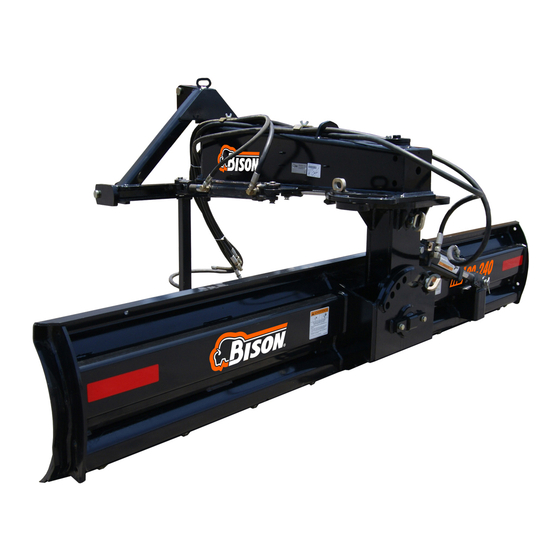
REAR BLADE
OPERATOR'S MANUAL
NB
NB
Models
NB80-180 • NB80-210 • NB80-240 • NB80-270
NB120-210 • NB120-240 • NB120-270 • NB120-300
Part №
4350-2147-03
Table of
Contents
Previous
Page
Next
Page
1
2
3
4
5
Advertisement
Table of Contents
Need help?
Do you have a question about the NB Series and is the answer not in the manual?
Ask a question
Questions and answers
Related Manuals for Bison NB Series
Construction Equipment Bison NB80-210 Operator's Manual
Rear blade (72 pages)
Construction Equipment Bison NB80-240 Operator's Manual
Rear blade (72 pages)
Construction Equipment Bison NB80-270 Operator's Manual
Rear blade (72 pages)
Construction Equipment Bison NB120-240 Operator's Manual
Rear blade (72 pages)
This manual is also suitable for:
Nb80-180
Nb80-210
Nb80-240
Nb80-270
Nb120-210
Nb120-240
...
Show all
Nb120-270
Nb120-300
Table of Contents
Print
Rename the bookmark
Delete bookmark?
Delete from my manuals?
Login
Sign In
OR
Sign in with Facebook
Sign in with Google
Upload manual
Upload from disk
Upload from URL


Need help?
Do you have a question about the NB Series and is the answer not in the manual?
Questions and answers