Sign In
Upload
Download
Table of Contents
Contents
Add to my manuals
Delete from my manuals
Share
URL of this page:
HTML Link:
Bookmark this page
Add
Manual will be automatically added to "My Manuals"
Print this page
×
Bookmark added
×
Added to my manuals
Manuals
Brands
Incon Manuals
Measuring Instruments
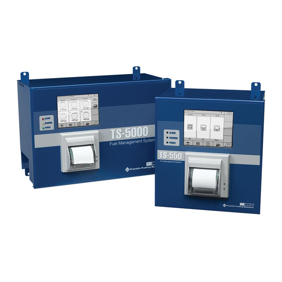
TS-550
Installation & user manual
Incon TS-550 Installation & User Manual
Hide thumbs
1
2
Table Of Contents
3
4
5
6
7
8
9
10
11
12
13
14
15
16
17
18
19
20
21
22
23
24
25
26
27
28
page
of
28
Go
/
28
Contents
Table of Contents
Bookmarks
Table of Contents
Table of Contents
Notice
Important Safety Messages
Overview
Applications
Site Requirements
Available Configurations
Installation
SCM Setup (Console Programming)
AC Input Module
4-20Ma Input Module
Relay Module
Turbine Pump Interface (TPI) Applications (Alternate STP Control)
Secondary Containment Monitoring Application
SCM Status and Control Screens
SCM Status Summary Screen
SCM Control Screen
Status Indicator Table
Control Indicator Table
Learn Indicator Table
Pre-Operational Containment Testing
Required Equipment
Containment Tightness and Continuity Test
STP Siphon Flow Rate Test
Learn Process
When to Learn/Re-Learn
Procedure
Learn Messages
SCM Reports
SCM Alarm Reports
Application Event Reports
Alarms
SCM Alarms and Warnings
Clearing Alarms
Enabling/Disabling SCM
Enabling SCM Channels
Disabling SCM Channels
SCM Annual Functional Testing
Advertisement
Quick Links
1
Available Configurations
2
Scm Setup (Console Programming)
3
Ac Input Module
4
Alarms
5
Scm Alarms and Warnings
6
Clearing Alarms
Download this manual
Secondary Containment Monitoring
Installation & User's Guide
TS-550/TS-5000 consoles
Franklin Fueling Systems • 3760 Marsh Rd. • Madison, WI 53718 USA
Tel: +1 608 838 8786 • 800 225 9787 • Fax: +1 608 838 6433 • www.franklinfueling.com
Table of
Contents
Previous
Page
Next
Page
1
2
3
4
5
Advertisement
Table of Contents
Need help?
Do you have a question about the TS-550 and is the answer not in the manual?
Ask a question
Questions and answers
Related Manuals for Incon TS-550
Measuring Instruments Incon task sentinel TS-1001 Programming Manual
Automatic tank gauge leak detection system (184 pages)
Measuring Instruments Incon task sentinel TS-2001 Programming Manual
Automatic tank gauge leak detection system (184 pages)
Measuring Instruments Incon task sentinel TS-504 Programming Manual
Automatic tank gauge leak detection system (184 pages)
Measuring Instruments Incon task sentinel TS-750 Programming Manual
Automatic tank gauge leak detection system (184 pages)
Measuring Instruments Incon TS-5000 Installation & User Manual
(28 pages)
Measuring Instruments Incon 1250B Installation And Programming Manual
Programmable position monitor (36 pages)
Measuring Instruments Incon OPTImizer 2 User Manual
On-line circuit breaker performance and sf6 gas density monitor (74 pages)
This manual is also suitable for:
Ts-5000
Table of Contents
Save PDF
Print
Rename the bookmark
Delete bookmark?
Delete from my manuals?
Login
Sign In
OR
Sign in with Facebook
Sign in with Google
Upload manual
Upload from disk
Upload from URL


Need help?
Do you have a question about the TS-550 and is the answer not in the manual?
Questions and answers