
Subscribe to Our Youtube Channel
Related Manuals for Incon 1250B


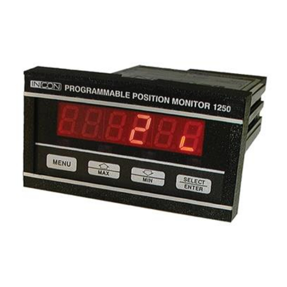
Summary of Contents for Incon 1250B
- Page 1 INSTALLATION AND PROGRAMMING MANUAL FOR MODEL 1250B PROGRAMMABLE POSITION MONITOR Solid State Synchro Indicator for Synchro Transmitter (For use with firmware revision 4.04 or higher) 000-1077 Rev. J...
-
Page 2: Table Of Contents
Sales & Customer Service: 800-225-9787 Technical Service 207-571-1202 Web Site: www.franklingrid.com E-mail: sales@franklingrid.com This manual applies to all INCON model 1250B monitors with firmware revision 4.04 or higher Copyright 2000, 2001,2002, 2003, 2008, 2017, Intelligent Controls, Inc. All rights reserved... -
Page 3: List Of Figures
LIST OF FIGURES Figure: Page: Mechanical Dimensions ..……………………………………………………….. Field Wiring Diagram ..………………………………………………………….. 5 Field Wiring Diagram with 4-20mA Option …………………………………….. 5 Analog Configuration Switches and Trim Pots ………………………………….. 7 Simplified Programming Flowchart …...………………………………………… 8 Linear Scaling Mode Analog Output ...………………………………………….. 15 Non-Linear Scaling Mode Analog Output ...…………………………………….. -
Page 4: Introduction
The 1250B may be programmed to perform mathematical scaling and offsetting of the rotational position of the synchro transmitter. A special feature of the 1250B is its capability to monitor up to 100 definable position segments. This is particularly suited to monitoring power transformer load tap changer position, where the desired readout is in whole tap numbers, and small discrepancies in position are masked. - Page 5 Figure 1.1 Mechanical Dimensions Figure 1.2 Field Wiring Diagram Figure 1.3 Field Wiring Diagram with 4-20mA Output...
- Page 6 ASCII Communication Protocol Enable MODBUS Communication Protocol Enable Spare High / Low Relay Limit Option Enable Analog Output Option Enable Spare Spare Spare Table 1.3 Digital Communication Connector Pin-Out 1250B DB-9 RS-232 RS-485 Comm RS-485 Pin# Pin# Function Port Adapter Pin #...
- Page 7 4) When additional remote indication is needed, several 1250Bs may be wired in parallel to the same transmitter, or the INCON RD-4 Remote Indicator can be used. 5) The 1250B and the synchro transmitter MUST BE WIRED TO THE SAME AC SOURCE. Do not remove the jumpers from terminals E and F.
- Page 8 Figure 2.1 Simplified Programming Flowchart...
-
Page 9: Programming
2.0 PROGRAMMING The Model 1250B has three methods of programming, numeric menu, alphanumeric menu, and serial port programming commands. Depending upon the serial port option ordered, the serial programming commands will be either RS-232 ASCII commands or RS- 485 packet commands. (See Table 2.1 for a full listing of all programming menu items. See Figure 2.1 for a simple programming flowchart. - Page 10 Num- Alpha-numeric Default Programmable Function: eric Protocol Value: Range: OP 25 rL Ht Any valid tap number Segmented Mode: Sets high relay limit tap OP 27 S Pt Any valid tap number Segmented Mode: Sets present tap position OP 28 L Pt Any valid tap number Segmented Mode: Loads present tap...
-
Page 11: Serial Programming
The terminal must have the proper Comm port settings to communicate to the 1250B (see section 3.3). See Table 2.2 for a full listing of all programming commands and syntax. At the command prompt, type a command followed by the new parameter setting, using proper syntax as shown in Table 2.2. - Page 12 Command Syntax: Function: Explanation: TEDIT◊n◊x.xxxx Replace data point pair #n with a Will possibly re-number entries in the ◊y.yyyy new data pair x.xxxx,y.yyyy table (X=Degrees, Y= Conv. Value) TDELETE◊n Delete data point pair #n from Will re-number entries in the table the N.L.
- Page 13 INCON has devised a solution to these problems. Two types of position filtering have been added to the 1250B’s firmware – a Turns Rate Threshold Filter, and an Averaging Filter. The strength of each filter can be adjusted so that the best combination can be achieved for individual applications.
- Page 14 “FA 25” error code when the synchro signal is lost. The 1250B has an item in the programming menu which allows the “automatic reset” portion of this feature to be enabled or disabled.
- Page 15 This mode is used when the desired display and corresponding analog output signal is continuously variable. The synchro transmitter could stop in any position and the 1250B must give a corresponding position reading. The analog output corresponds to the continuously variable position, between minimum and maximum limits.
- Page 16 The 1250B is capable of non-linear conversion / correction. Whenever there are two or more data point pairs in the conversion table the 1250B will automatically switch to non- linear scaled mode. Conversion table data point pairs may be added manually or “learned”...
- Page 17 Modes 16 & 17: Base 1 Uni-polar Segmented These modes are used for LTC monitoring when the lowest tap number is 1. There may be multiple neutral taps. They can be located anywhere between the lowest and highest taps as long as they are grouped together in one section. Mode 16 has a linear analog output that continuously varies with LTC shaft position.
- Page 18 Modes 18 & 19: Base 0 Uni-polar Segmented These modes are used for LTC monitoring when the lowest tap number is 0. There may be multiple neutral taps, which can be located anywhere between the lowest and highest taps as long as they are grouped together in one section.
- Page 19 Modes 20 & 21: Bi-polar Segmented These modes are used for LTC monitoring when the neutral tap(s) are in the center of the dial and there is an equal number of raised and lowered taps. There may be multiple neutral taps, which can be located anywhere between the lowest and highest taps as long as they are grouped together in one section.
- Page 20 Programming Notes: If the Degrees Per Tap value is not known, the 1250B can be used to determine this value. Follow these steps to determine the Degrees Per Tap value: 1) Program the 1250B for Linear Scaled Mode as follows:...
-
Page 21: Options
If the presence of high voltage AC “ripple” is found on the analog output terminals, it is generally not a problem with the 1250B itself. Check the isolation of all field wiring with respect to earth ground. All wiring should be completely isolated from ground. See section 3.2 Input Isolation Option. -
Page 22: Input Isolation
OFF state an error message “ERR 1” will appear when attempting to set relay limits. If the 1250B is programmed for a Scaled Mode, use the OP 7, rLY L, RLYLOW command to set the Low Relay Limit and the OP 8, rLY H, RLYHIGH command to set the High Relay Limit. -
Page 23: Serial Rs-232
Polled Mode When this mode is selected, the 1250B can be interrogated at any time via the RS-232 port for the current position. This is done by first instructing the 1250B to latch the current position by transmitting an asterisk (*) to the unit. The position is then extracted, one character at a time, by transmitting the digits 0 through 6. -
Page 24: Serial Rs-485 Modbus
Model RD4 Remote Display. It causes the 1250B’s RS-232 output to transmit the proper protocol and timing for the RD4 to mimic what is on the 1250B’s display. To select this mode, use the menu command OP 51, RS232 command to choose mode “7”. - Page 25 Data Block = Begins with the number of the first register (two bytes) in a command packet, or data from the first register (two bytes) in a response packet. Followed by the number of registers to be read (two bytes) in a command packet, or by data from subsequent registers. Last 2 Bytes = Error Checking CRC –...
- Page 26 Table 3.5 Write Registers Command Format Device Function # of First # of First # of Registers # of Registers Address Code Register to be Register to be to Write to Write Char written to written to Byte Program Data for Program Data for Program Data for Program Data for...
- Page 27 In the following Table 3.8, the meanings of the columns are as follows: Register: MODBUS register address as seen in a MODBUS command beginning with register 40001 and ending with 49220. These addresses are in decimal. The same register’s address in hexadecimal, this value is calculated by Hex: subtracting 40001 from the register number.
- Page 28 Table 3.8 RS-485 MODBUS Register Definitions Register: Hex: Function: Binary Format: 40001 0000 setup / run 000000000000000s Read/Write mode select LSB (s) selects mode 0 – run mode 1 – setup mode (must be 1 before any program parameter can be changed) 40002 0001 synchro input...
- Page 29 Register: Hex: Function: Binary Format: 44103, 44104 1006,1007 analog high limit bcdabcdbbcdcbcdd bcde000000vspppp Read/Write 44353 1100 number of taps 000000000nnnnnnn 7 LSBs Read/Write 44354, 44355 1101,1102 degrees per bcdabcdbbcdcbcdd bcde000000vspppp Read/Write segment 44356 1103 number of 000000000000nnnn 4 LSBs Read/Write neutrals 44357 1104...
- Page 30 Register: Hex: Function: Binary Format: 110=remote display driver 45634 1601 baud 000000000000bbbb 4 LSBs (bbbb) Read/Write 0000=300, 0001=1200, 0010=2400, 0011=4800, 0100=9600, 0101=14400, 0110=19200, 0111=28800, 1000=38400, 1001=57600, 1010=76800 45635 1602 word length 000000000000000w LSB (w) select Read/Write 0 = 7 bits, 1 = 8 bits 45636 1603 parity...
- Page 31 Step 1: First Command; Write the X and Y values (Y only when learning a position) into registers 45891, 45892 (1702h, 1703h) and 45893, 45894 (1704h, 1705h) respectively. Step 2: Second Command; Write the “add to table” (010) command, or the “add learned table position” (101) command to register 45889 (1700h).
-
Page 32: Field Calibration And Test
This toggles the output between LOW, MID, and HIGH outputs. The display on the 1250B should read “LO”. The analog output low scale may now be adjusted by turning the “ZERO” pot, accessible through the slot in the right side of the case (see Figure 4.1), until the output signal is reading properly on the multi-meter. - Page 33 Cold Boot: The 1250B has the capability to delete all user-programmed values and restore all factory default program values. This “cold boot” is accomplished by pressing the “MENU” key while turning on the power to the 1250B. There is no way to undo the effects of a cold boot.
-
Page 34: Error Codes
5.0 Error Codes Table 5.1 Error Codes DISPLAY DESCRIPTION Watchdog Re-start (Processor Crash) If the condition recurs, call Technical FA 2 Service. Memory Error at start-up FA 3 (User programming is erased; Factory program defaults are re-loaded) FA 5 Keyboard Error at Start Up (Up or Down Key, or more than one key is being pressed during Power-Up) Input Calibration Error (Input signal differential too large) FA 20... -
Page 35: Specifications
6.0 Specifications (All values are typical, unless otherwise specified) ENCLOSURE: RECTANGULAR PANEL MOUNTED METER MATERIAL PLASTIC SIZE 89mm W X 41.3mm H X 178mm D BEZEL 112mm W X 62mm h X 17.5mm D MOUNTING INTEGRAL SNAP-IN TABS POWER INPUT: CONNECTOR SCREW TERMINALS L1, L2, GND VOLTAGE... - Page 36 Model 1250B Installation & Programming Manual...
Need help?
Do you have a question about the 1250B and is the answer not in the manual?
Questions and answers