
Subscribe to Our Youtube Channel
Related Manuals for Incon OPTImizer 2


Summary of Contents for Incon OPTImizer 2
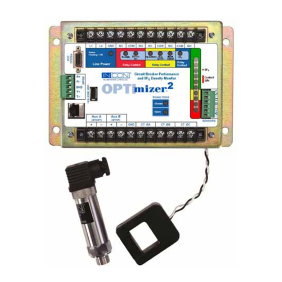
- Page 1 OPTImizer ® On-Line Circuit Breaker Performance And SF Gas Density Monitor User’s Guide OPTImizer INCON P.O Box 638, Saco, Me. 04072 Tel: 207-283-0156 Fax: 207-238-0158 ©2012 000-1530 Rev C...
- Page 2 INCON (Intelligent Controls) reserves the right to change this document and specifications at any time without notice. INCON makes no express or implied warranty with regard to the content of this manual. INCON assumes no liability for errors or omissions, or for any damages, direct or consequential, that may result from the use of this mizer document or the equipment that it describes.
-
Page 3: Table Of Contents
Contents List of Tables ........................... 6 1 INTRODUCTION ......................7 1.1 Overview .......................... 7 1.2 Operation Overview ......................7 2 INSTALLATION ......................10 2.1 External Connections (Termination) ................10 2.2 Mounting Dimensions ....................11 2.3 SF Sensor Mounting ....................13 General Planning Considerations....................15 3 APPLICATION GUIDE ....................17 3.1 Breaker Wear Symptoms .................... - Page 4 5 User Interface ......................54 5.1 Post Maintenance Resetting / Presetting ................ 54 5.2 Periodic Data Dump ......................54 Alarm History Report ........................55 Application Event History Report....................56 Circuit Breaker Event History Report ..................57 Logged History Report ......................58 Daily Summary Report ......................
- Page 5 List of Figures mizer Figure 1: OPTI Field Wiring ..................10 mizer Figure 2: OPTI Mounting Dimensions (Not actual size) ........... 11 mizer Figure 3: OPTI General Dimensions ................. 12 Figure 4: DSDP Sensor Connections ................... 13 Figure 5: Breaker Cabinet and Control House Interface ............15 Figure 6: Typical Trip Trace, with Arc Duration Information Superimposed ......
-
Page 6: List Of Tables
List of Tables Table 1: Required Information for Application ............... 14 Table 2A: Breaker Cabinet Installation Considerations ............16 Table 2B: Control House Installation Considerations ............16 Table 3: Alarm Set-points ...................... 26 Table 4: Alarm Outputs, LED’s and Relays ................26 Table 5: Impact of A Input Assertion on the A Input Delay Setting ........ -
Page 7: Introduction
One, two or three Two types of SF gas density sensors may be used: gas density sensors may be used. 2-wire 4-20mA “analog” or INCON Model DSSP “digital” type sensor. This input is user-configurable for up to mizer The OPTI is specifically designed for use on gas three sensors. - Page 8 DC Input Channels FIELD OUTPUTS Two discrete voltage signals, 48-250 VDC. The “Aux A” Visual Display input is used to initiate the trip time log, the mechanism On-board LEDs will illuminate and latch when reaching an time log, the arc duration time log, and the cumulative alarm setpoint or detecting a failure mode.
- Page 9 OPTImizer² can be accessed remotely with a web browser, providing the correct IP address is given. Firmware upgrades can also be performed through this port using a special upgrade tool (contact INCON Technical Services). USB COMMUNICATION PORT This port is for data dumping (BIN files and ASCII text files), alarm acknowledgement or firmware upgrades.
-
Page 10: Installation
I N S T A L L A T I O N 2.1 External Connections (Termination) 110-250 VDC (Twisted Pair Recommended) 90-264 VAC 50/60Hz Terminal Screw maximum torque Contact Rating: 3A @ 250 VAC or 12 inch-Lbs 1/2A @ 125VDC Density Sensors The OPTImizer should be installed... -
Page 11: Mounting Dimensions
2.2 Mounting Dimensions Figure 2: OPTImizer² Mounting Dimensions (Not actual size) -
Page 12: Figure 3: Opti Mizer 2 General Dimensions
OPTImizer² General Dimensions Figure 3:... -
Page 13: Sf Sensor Mounting
Caution installing sensors. A gas-tight seal The INCON DSDP is a “true density” sensor, not a must be achieved on all pipe fitting and temperature-compensated pressure sensor. For this sensor threads. -
Page 14: Table 1: Required Information For Application
2.4 Planning for Installation and Programming, Required Field Documentation mizer The OPTI application should be planned, much like the application of other IEDs, such as a protective relay, fault recorder, or monitor. Actual programming and installation can be accomplished in a few hours (typically 2 hours) after the setpoints are calculated and determined. -
Page 15: General Planning Considerations
General Planning Considerations mizer The OPTI may be installed in a control house or breaker cabinet. The required interfaces can be obtained at either location. The SF sensors must be installed on the circuit breaker itself. Sensor accuracy is best when installed nearest to the interrupter vessel. -
Page 16: Table 2A: Breaker Cabinet Installation Considerations
The actual installation location may be determined after review of many factors, some of which are outlined below: Circuit Breaker Cabinet Mounting Pros Cons Trip initiate signal may not be available should Readily accessible to Maintenance personnel. it be the desired interface for the Aux A input assertion. -
Page 17: Application Guide
3 APPLICATION GUIDE Dielectric Capability The ability of a circuit breaker to extinguish an arc can 3.1 Breaker Wear Symptoms be monitored by examining the amount of time an arc is present after a trip command to the breaker is given. If the Breaker Wear Symptoms mechanism transit time remains constant, but an increase Power circuit breakers exhibit symptoms of wear from... -
Page 18: Description Of Circuit Breaker Monitoring
3.2 Description of Circuit Breaker Monitoring Typical Trip Trace Example mizer A typical trip trace is illustrated in Figure 6. The OPTI , by examining signals corresponding the start of the trip (trip initiate or the 52 / a contact opening), the end of mechanism travel (green light or 52 / b contact closing), and secondary phase currents can obtain a wealth of information about the power circuit breaker. -
Page 19: Interface To The Breaker Control Circuits
Interface to the Breaker Control Circuits INPUT MODE The Aux Input logic mode can be programmed for one of Two discrete voltage inputs are used to obtain information four conditions: to determine the start of the trip (Aux A) and the end of mechanism travel (Aux B). - Page 20 TRAVEL TIME (Mechanism Time Log) (Input Modes 1 & 4 only) When INPUT MODE 1 or 4 is selected, the OPTImizer² will record mechanism TRAVEL TIME. The mechanism time log consists of a timer. The timer starts from an assertion (or de-assertion in Mode 4) of the “Aux A” input, and stops with an assertion to the “Aux B”...
-
Page 21: T Or I X T Wear Duty
CLEARING TIME (Clearing Time Log) (Input Modes 2 & 4 only) The individual, phase-segregated CLEARING TIME logs use a timer, with the starting point at the beginning of the Trip signal and ending with the cessation of current in each phase. Thus the Clearing Time for each phase is the sum of the measured TRIP TIME and ARC TIME. -
Page 22: Time Line To Trip Trace Correlation (Examples)
Time Line to Trip Trace Correlation (Examples) mizer The following examples show how the OPTI logs events. They include: • Arc record examples • Interactions of the Aux A and Aux B inputs • The phase currents • The A INPUT DELAY setpoint •... -
Page 23: Figure 6B: Event To Time Correlation Of Fig 4
Figure 6B: Event to Time Correlation of Fig 6A, mizer Using Trip Coil Voltage to Start OPTI Example: mizer • The Aux A input on the OPTI is asserted by the Trip Signal voltage measured across the Trip Coil. • The recorded TRIP TIME is 25mS •... -
Page 24: Figure 6C: Event To Time Correlation Of Fig 4
Figure 6C: Event to Time Correlation of Fig 6A mizer Using a Separately Wetted 52 / a Contact to Start OPTI Measurements Example: • The Aux A input on the OPTImizer is asserted by voltage from a separate contact on the 52 / a switch. •... -
Page 25: Figure 7: Trip Trace, Using Trip Initiate To Start Opti Mizer 2
Total Arc Duration = 32mS A Input Delay = +24 AD = +24 "Aux A" input Current "Aux B" input TIME (mS) Aux A Input asserts at T Main Contacts open at T=24mS Arc Extingushes at T=56mS Arc Duration 56mS minus 24mS=32mS Aux B Input asserts at T=94mS Aux A assertion is 24mS earlier than Mains Parting A Input Delay = +24... -
Page 26: Alarm Set-Points
Alarm Set-points The following recorded parameters have alarm set-points placed against them. Specifically, these alarm points are: Parameter Units Range eTpOINT eSOLUTION Trip Time 0-999 mS Arc Time 1 mS 0-165 mS Clearing Time 0-265 mS Travel Time 1 mS 0-265 mS Contact Life Warning Percent... -
Page 27: Figure 8: Alarm Relay Assignments
Viewed graphically, the alarm relay assignments are: I²T Danger Restrike Excess Arc Duration Excess Clearing Time Excess Trip Time A-B Input Logic Excess Travel Time I²T Warning Yellow Operations Count No Operations Excess Closing Time Failed CT Pickup Internal Error Input Invalid Unknown CB Monitor Activity Low Gas... -
Page 28: Description Of Sf 6 Density Monitoring
SF gas density sensors: mass, change in mass and accumulated mass loss. Analog (4-20mA) and Digital (INCON DSDP). Both types At any time, when a warning or alarm occurs, its mizer are connected to the OPTI with two wires. -
Page 29: Programming
4 PROGRAMMING Initial Communication With the OPTImizer2 mizer To initialize communications with an OPTI , use the provided “crossover” cable to connect the Ethernet port on the mizer mizer OPTI to the Ethernet port on a computer. Power-up the OPTI and computer, then set the computer’s IP address to “192.12.27.2”... - Page 30 5. In the Local Area Connection Properties dialog box, under “This connection uses the following items,” select Internet Protocol (TCP / IP) and click Properties. 6. Select Use the following IP address. 7. Enter the IP address “192.12.27.2” Subnet Mask: Masking is a way to diversify the use of multiple subnets. The mask must match that of the network the mizer OPTI is connected to.
- Page 31 Windows 7™ Below is shown one way to configure the connection using Windows 7™. 1. Open Windows™ Explorer and right-click on Network. 2. Select Properties. 3. Select Change Adapter Settings...
- Page 32 4. The screen should show the Local Area Connection. Right click on the connection and select Properties. 7. Enter the IP address 192.12.27.2 5. Select Internet Protocol Version 4 (TCP/IPv4) 6. Select Properties...
-
Page 33: Initial Set-Up
1. Check the status of your connection by going to the Network Connections window. 2. If the connection status is disabled, enable it by right-clicking on the Local Area Connection and selecting Enable. If technical difficulties arise, please contact INCON Technical Support before proceeding. mizer Open the web browser. -
Page 34: Figure 10: User Interface, Confirming Configuration Update
Figure 10: User Interface, Confirming Configuration Update Following the guidelines listed in this manual, make the appropriate changes to each configuration parameter. When all changes are entered, click “Yes” to update the configuration. The correct Administrator’s password (initially set to “admin”) will need to be given for the changes to be saved. -
Page 35: General
Passwords are limited to a information to an IP address. This is used by INCON maximum of 40 characters. The password can contain Technical Service to help in troubleshooting. It should upper and lower case letters and any keyboard character. -
Page 36: Circuit Breaker Information
4.3 Circuit Breaker Monitor Settings CIRCUIT BREAKER INFORMATION mizer The OPTI can store information about the mizer The following settings are used by the OPTI circuit breaker in memory. This information is for specifically for circuit breaker monitoring. reference only. It has no effect on functionality. POWER SYSTEM FREQUENCY The applied power line frequency is entered as 60 or 50 Hz. -
Page 37: Figure 12: Aux A Interface, Using Trip Initiate (Red Light)
A INPUT POLARITY • Trip Command - One of the trip initiate contacts (Aux A Input Assertion Level) closes, shunting the red light and the Aux A input. This causes high current to flow through the trip coil, Entering the proper Aux A input assertion level allows the which begins to pull the latch. -
Page 38: Figure 13: Aux A Interface, Using 52 / A Contact In Trip Circuit
52/a OPTImizer 52/a OPTImizer A Input Polarity Aux A Aux A = Positive Input Input Trip Open Closed A Input Polarity = Positive Figure 14: Aux A Interface, using Trip Coil Excitation Voltage This is an elementary diagram of a typical trip circuit. The Closed Open elements T / 1 and T / 2 are trip-initiating contacts. -
Page 39: Figure 15: Aux A Interface Using Individually Wetted 52 / A Contact
B INPUT POLARITY (Aux B Input Assertion Level) Entering the proper Aux B input assertion level allows the mizer OPTI to properly stop the mechanism time log. The mizer OPTI reacts to a change in voltage state when the breaker is proceeding from the closed position to the open 52/a mizer position. -
Page 40: Figure 17: Aux B Interface, Using 52 / B Contact In Green Light Circuit
mizer In summation, the OPTI , when applied in parallel with the green light, should be set as: 52/b • B Input Polarity = “Positive”. OPTImizer OPTImizer Aux B 52/b Input Aux B Input B Input Polarity = Positive Closed Open B Input Polarity Figure 18: Aux B Interface, using Individually Wetted 52 / b = Negative... -
Page 41: Input Mode
Input Mode Mode 2 = Momentary A Signal, No B Signal Entering the Input Mode, in combination with the A Input Mode 3 = Continuous A Signal, No B Signal mizer Polarity and B Input Polarity, allows The OPTI Mode 4 = Momentary A Signal with Continuous B monitor the circuit breaker control circuit’s logic states Signal in the closed and open positions. -
Page 42: Table 5: Impact Of A Input Assertion On The A Input Delay Setting
Depending on what is being used to assert the Aux A input, there are multiple methods available to derive the A Input Delay setting value. A Input Assertion Methods to Derive A INPUT DELAY Setting • Use breaker trip trace, A Input Delay setting is the time difference between the trip initiate signal and the parting of the main contacts Parallel connection to “Red Light”... -
Page 43: Contact Wear Mode
Contact Wear Mode Use of ANSI / IEEE C37.06-1989, Rating of Power Circuit Breakers under a Symmetrical Fault Basis mizer The OPTI can be programmed to use one of ANSI / IEEE C37.06-1989 can provide guidance for the two available Contact Wear modes, I x T or I T. -
Page 44: Figure 21: Estimated Arc Time Based On Nameplate Breaker Voltage
Example: Given: Breaker is rated at 69kV, 20kA fault interrupt (symmetrical), 1200A rated load break. No information is given on the number of fault rated interruptions. Assume: 69kV breakers have an arc duration T of 24mS (0.024s). 69kV breaker can withstand 100 rated load break operations, N , before an inspection (ANSI / IEEE C37.06-1989). -
Page 45: If Breaker Is Rated In Mva, And Is Being Applied At Voltage Other Than Nameplate
If breaker is Rated in MVA, and is being Set at One Fault Rated Interruption less than the Danger Limit Applied at Voltage other than Nameplate: There are occasions when the breaker is rated in MVA Setting the Warning Limit at one fault interruption operation at a given voltage, and the breaker is being applied at a allows a Warning alarm to be issued before another different voltage. -
Page 46: Arc Time Alarm Limit
Arc Time Alarm Limit Travel Time Alarm Limit mizer mizer The OPTI will measure the duration of the The OPTI will measure the time between the opening of the 52a switch and the closing of the 52b fault arcs as the interrupter contacts separate. An Arc switch, if programmed for Input Modes 1 or 4. -
Page 47: Operations Count Alarm Limit
Operations Count Alarm Limit Restrike Alarm The ability to detect restrikes is important, especially for mizer The OPTI will increment a counter with each gas (SF ) breakers. circuit breaker trip operation. An Operations Count Alarm Limit may be set to turn on the Operations LED and mizer The following figure illustrates how the OPTI close the Yellow relay when the breaker has reached a... -
Page 48: Figure 22A: A 3-Cycle Arc, No Restrike
Arc begins here Arc Time = 3 Cycles Restrike not detected Possible total arc duration = 10 cycles Figure 22A: A 3-Cycle Arc, No Restrike Arc begins here Less than ¼ cycle Arc Time = 5.5 Cycles Restrike not detected Possible total arc duration = 10 cycles Figure 22B, A 5½-Cycle Arc, No Restrike Arc begins here... -
Page 49: Sf Monitor Settings
4.4 SF MONITOR SETTINGS Low Gas Alarm Limit An alarm will be asserted when the density or pressure mizer The following settings are used by the OPTI reaches or falls below the programmed Low Gas Alarm specifically for SF monitoring. Limit. -
Page 50: Sf Sensor Signals
Note: When the OPTI is cold-started, the Signal width-modulated signal (INCON DSDP) Low Represents parameter is set to 0.0 g / L. Each of the three input channels can be separately To set the Signal Low Represents parameter, select the programmed for an Analog or Digital sensor or disabled CONFIGURATION tab and click “EDIT”:... -
Page 51: Actions
4.5 ACTIONS Calculation Method of presetting Remaining Contact Life An “Action” is taken in response to an alarm or In the calculation method, an attempt is made to maintenance activity. Actions include clearing active quantify the cumulative currents interrupted since the alarms;... -
Page 52: Preset Operation Number
Clear Latched Alarms Example for Calculating Accumulated Duty Wear Given: A breaker has operated 8 times since the last When an alarm occurs, an LED will be lit to give a general refurbishing. The breaker is a 38 kV breaker. The indication of what has caused the alarm. -
Page 53: Reset Sf Density Trend Data
Reset SF Density Trend Data If an SF density sensor is found to be faulty, the SF Trend calculation should be re-started after replacing the sensor. This can be done by resetting the accumulated SF data for that channel. When this action is taken, a new array of data will be accumulated and a new SF Trend will be calculated for that channel. -
Page 54: User Interface
5 User Interface • The data can then be viewed, graphed, sorted, as desired. There are five general interface activities with the • See also page 59 for instructions for downloading OPTImizer2: mizer the complete OPTI database using a USB 1. -
Page 55: Alarm History Report
Alarm History Report The Alarm History Report consists of: Code; Category; Device; Data; State; (Date & Time) Occurred and (Date & Time) Cleared. Code: The alarm Code is an abbreviation for the description of the alarm seen on the ALARM tab. The prefix “al” is used to indicate that it is an Alarm code. -
Page 56: Application Event History Report
Application Event History Report Category: The alarm Category identifies what class the alarm belongs to: System, Circuit Breaker The Application Event History Report consists of: Code; Monitoring (CBM) or SF6 Monitoring. The prefix Category; Device; Data; (Date & Time) Occurred “alc”... -
Page 57: Circuit Breaker Event History Report
Circuit Breaker Event History Report • Type code “cbResetOperationCount” indicates that the event record was recorded because the The Circuit Breaker Event History Report consists of: Operation Counter was reset. • Report ID Operation Number: This number is associated with the •... -
Page 58: Sf Logged History Report
Logged History Report Data Interpreting The SF Logged History Report consists of: Record Circuit Breaker Data: ID; Time Stamp; Density (A,B,C); Pressure (A,B,C); mizer Data from the OPTI reveals absolute setpoint limit Temperature (A,B,C). violation and trends in degradation: Record ID: This is a number used by the system to identify •... - Page 59 Data • CONFIDENCE LEVELS indicate the statistical validity of the SF trends. A combination of two mizer Data from the OPTI can call attention to potential things affects the Confidence Level value: the gas leaks; long before critical gas levels are reached. amount of data collected and the linearity of the SF •...
-
Page 60: Alarm Acknowledgement / Cancellation
USB memory stick. These operations include: clearing alarms; downloading the full database; resetting the IP address; uploading new firmware. INCON Technical Support can provide these scripts on memory sticks or through e-mail. Clearing Alarms: All latched alarms will be automatically... -
Page 61: Communication Details
6 COMMUNICATION DETAILS 6.1 RS-232 mizer uses asynchronous RS-232 communications. It is configured as a DCE device. A 9-pin OPTI female connector is on the mizer for cable connection. The end of the cable that connects with OPTI mizer therefore is a 9-pin male. OPTI OPTIMIZER DTE Device... -
Page 62: Figure 26: 25-Pin To 9-Pin Cable Connections
OPTImizer DTE Device DCE Device (IN) DCD 8 1 DCD (OUT) Pins 1 and 4 are connected (IN) RXD 3 2 RXD (OUT) internally (OUT) TXD 2 3 TXD (IN) (OUT) DTR 20 4 DTR (IN) GND 7 5 GND 6 N/C (OUT) RTS 4 7 RTS (IN) -
Page 63: Fiber-Optic Interconnection
6.2 Fiber-Optic Interconnection mizer ’s serial port is configured to support the use of Schweitzer fiber-optic transceivers. OPTI A 9-pin female null modem adaptor must be used between the mizer and the transceiver. OPTI The transceiver will be powered directly from the mizer ’s serial port’s CTS line. -
Page 64: Xml
6.5 XML mizer will respond to manual XML commands. To access XML command mode, select the OPTI PREFERENCES page. Click on “EDIT” in the upper right. Figure 30: User Interface, Preferences Page Check the box next to “Show XML Tool”. Click “Yes”... -
Page 65: Figure 32: User Interface, Xml Page
Figure 32: User Interface, XML Page Click “Query”. The Command field can now be pulled down and an XML command selected. Click “Help” to view an explanation of the command and its proper syntax. Figure 33: User Interface, XML Command Access Once selected, a command can be executed by clicking “Send”. -
Page 66: Dnp3.0
6.6.1 Device Profile Document DNP V3.0 Device Profile Document (Also see the DNP Implementation Table, beginning on page 68) Vendor Name: Franklin Fueling Systems, Inc. INCON Power Reliability Systems Device Name: OPTImizer Highest DNP Level Supported: Device Function: For Requests:... - Page 67 Sends/Executes Control Operations: WRITE Binary Outputs: g Never 1 Always 1 Sometimes 1 Configurable SELECT/OPERATE: 1 Never g Always 1 Sometimes 1 Configurable DIRECT OPERATE: g Never 1 Always 1 Sometimes 1 Configurable DIRECT OPERATE – No ACK: g Never 1 Always 1 Sometimes 1 Configurable Count>1:...
-
Page 68: Dnp3.0 Implementation Table
6.6.2 DNP3.0 Implementation Table The following table identifies the variations, function codes, and qualifiers supported by the mizer DNP Slave in both request messages and in response messages. OPTI OBJECT REQUEST RESPONSE Object Variation Description Function Qualifier Code Function Code Qualifier Code (Hex) Number Number... -
Page 69: Dnp3.0 Point List
6.6.3 DNP3.0 Point List The following table identifies for each data type, the data points available in the device. Binary Input Points Slave >> Master Static (Steady-State) Object Number: 1 Change Event Object Number: 2 Static Variation reported when variation 0 requested: 1 (Binary Input 2 without status) Change Event Variation reported when variation 0 requested: 3 (Binary Input Change with Time) Event Point... - Page 70 Analog Input Points Slave >> Master Static (Steady-State) Object Number: (30,1) Change Event Object Number: (32,1) Static Variation reported when variation 0 requested: (30,1) Change Event Variation reported when variation 0 requested: (32,1) Event Point Default Default Name/Description Dead Band Class Index Group...
- Page 71 Counter Input Points Slave >> Master Static (Steady-State) Object Number: (20,1) Change Event Object Number: (22,1) Static Variation reported when variation 0 requested: (20,1) Change Event Variation reported when variation 0 requested: (22,1) Point Point Default Default Name/Description Index Index Group Variable Current Operation Number...
-
Page 72: Specifications
7 SPECIFICATIONS Electrical: Power Supply Input Voltage 110-250 VDC / 90-264 VAC, 50 / 60 Hz Aux A & B Input Voltage 0 to 48 - 250 VDC CT (Pickup Coil) Input Signal 0 to 5 VAC Input Sampling Rate 32 Samples per line cycle Analog: 4 to 20 mA Input Signal... -
Page 73: Dsdp Sf 6 Density & Temperature Sensor Specifications
DSDP SF Density & Temperature Sensor Specifications Principal: Oscillating Quartz Measurement Density Measuring Range: 0 to 60 Grams per Liter (kg/m3) SF Temperature Measuring Range: -40 to +85 Degrees Celsius Accuracy: +/- 1% of measured value and +/- 1% of range Repeatability: +/-0.2% of measured value Stability:... - Page 74 P.O Box 638, Saco, Me. 04072 Tel: 207-283-0156 Fax: 207-238-0158 ©2012 000-1530 Rev C...
Need help?
Do you have a question about the OPTImizer 2 and is the answer not in the manual?
Questions and answers