Table of Contents
Advertisement
Precautions
This document provides quick guidelines for hardware installation.
This document does not describe pre-delivery assembly. This document pertains to onsite installation.
Electrostatic Discharge
Put on ESD gloves or an ESD wrist strap before handling plugboards, boards, and IC chips to prevent damage to
sensitive components caused by electrostatic discharge from the human body. Ensure that the other end of the
ESD wrist strap is properly grounded.
Binding Cables
The binding intervals between cable ties or fiber binding straps inside a cabinet must not exceed 250 mm.
The interval must not exceed 200 mm for user cables inside a cabinet.
If a cable trough passes two through beams, binding intervals between cable ties for all cables and
corrugated pipes outside a cabinet are determined by the distance between the two beams. If a cable trough
does not pass through beams, the binding interval between cable ties must not exceed 250 mm.
Pre-installation Check
Check that the equipment room, cabinet, power supply, ground cables, optical cables, and associated
facilities are all ready prior to installation.
Installation Environment
The device does not have an air filter. It is recommended that the air filter be dustproof at the cabinet level.
This device is a class A product, which can only be installed indoors.
A product and may cause radio interference in a living environment. In this case, you may need to take
feasible measures for the radio interference.
Devices such as wireless antennas cannot be installed in the equipment room. If the devices must be
installed, they must be lower than the electromagnetic environment requirements (for details, see the
electromagnetic environment requirements) or add necessary electromagnetic shielding measures.
1
Advertisement
Table of Contents

Related Manuals for Huawei NetEngine-8000-M8


Summary of Contents for Huawei NetEngine-8000-M8
- Page 1 Precautions This document provides quick guidelines for hardware installation. This document does not describe pre-delivery assembly. This document pertains to onsite installation. Electrostatic Discharge Put on ESD gloves or an ESD wrist strap before handling plugboards, boards, and IC chips to prevent damage to sensitive components caused by electrostatic discharge from the human body.
- Page 2 Instructions and Precautions for Handling Boards Always put on an ESD wrist strap or ESD gloves before handling a board. Wearing ESD gloves Wearing an ESD wrist strap Holding a board without ESD protection Hold the ejector levers of a board with both hands. Do not touch any board chips, circuits, or other components.
-
Page 3: Tools For Installation
Tools for Installation Phillips screwdriver Flat-head screwdriver Long measuring tape Level Adjustable wrench (M2-M6) (M2-M6) Socket wrench Torque wrench Hex key Crimping tool Wire clippers Wire stripper RJ45 crimping tool Diagonal pliers COAX crimping tool Needle-nose pliers Open-end wrench Combination pliers File Multimeter Heat gun... -
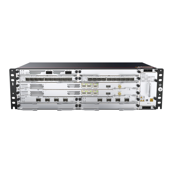
Page 4: Installing A Chassis
Installing a Chassis Introduction to a Chassis Chassis Power Board Fan Board Interface Board Control Board... - Page 5 Cabinet Installation Guide delivered with a cabinet. consumption of all devices in the cabinet is less than or Huawei A63B cabinet is recommended. If customers choose to purchase cabinets by themselves, the cabinets must meet the following requirements: equal to the heat dissipation capability of the cabinet.
- Page 6 Installing a Chassis in Cabinet Installing a Chassis in a Standard 19-Inch Cabinet Floating nut Mounting hole When tightening floating nuts, ensure a minimum distance of 75 mm between a chassis side and its 5.5±0.5 Kgf· cm adjacent column for ventilation. Install the cable management frame and power Fix floating nuts and M6 screws in the correct holes.
- Page 7 Installing a Chassis in an ETSI Cabinet with Front Columns Mounting hole Floating nut When tightening floating nuts, ensure a minimum 5.5±0.5 Kgf· cm distance of 75 mm between a chassis side and its adjacent column for ventilation. Fix floating nuts and M6 screws in the correct Install the cable management frame and power holes.
- Page 8 Installing a Chassis in an ETSI Cabinet with Front Columns 30±3 Kgf· cm Install the chassis in the cabinet.
- Page 9 Installing a Chassis in an ETSI Cabinet with Middle Columns 5.5±0.5 Kgf· cm When tightening floating nuts, ensure a minimum distance of 75 mm between a chassis side and its adjacent column for ventilation. Fix floating nuts and M6 screws in the correct Install the cable management frame and power holes.
- Page 10 Installing a Chassis in an ETSI Cabinet with Middle Columns Connect the PGND cable to the ground point on a column of the cabinet or to an indoor ground bar. 12±1.2 Kgf· cm 30±3 Kgf· cm Install the 19-inch mounting ears and conversion Attach a PGND cable to the chassis.
- Page 11 Installing Boards and Components Installing Boards • Loosen the screws on a filler panel, and remove the filler panel. • Hold the ejector levers on the front panel of a board and raise them to form an angle of approximately 45 degrees with the front panel.
-
Page 12: Installing A Fan
Installing a Fan The fan module must be aligned with and inserted into the slot of the chassis properly. Installing a Fan Installing a Power Board • The power module must be aligned with and inserted into the slot of the chassis properly. •... -
Page 13: Installing The Power Cables
Installing Fibers and Cables Common Cables for the Chassis PGND cable DC power cable Fiber Shielded network cable E1 cable (120-ohm) E1 cable (75-ohm) Installing the Power Cables Installing the DC Power Cable Check the fuse current of the external power supply. Max. - Page 14 The electrical conductor of a power cable must be completely inserted into a DC connector to protect you from a possible electric shock. Shut down power supplies before connecting or removing a power cable. Power cables must be connected according to indications on the PIU board. If the power cables are not connected correctly, the equipment cannot be powered on.
- Page 15 Installing Ethernet Service Cables In a flat door cabinet, the number of shielded network cables must be limited. For example, a maximum of six N63B/N63E single-layer boards can be configured for the 300 deep flat cabinet, and the number of shielded network cables can be added to the convex door cabinet.
- Page 16 Installing Fibers Within and Outside a Cabinet Installing Fibers for Chassis When installing or maintaining fibers, do not look into optical ports without eye protection. Before installing and routing fibers within a cabinet, install FOAs on optical ports according to the FOA installation list. When the recommended A63B cabinet is adopted, you are advised to add only one optical attenuator.
- Page 17 Installing Fibers Outside a Cabinet • Do not feed more than 60 fibers with a diameter of 2 mm in an open corrugated pipe with a diameter of 32 mm. When installing a corrugated pipe, route it approximately 10 cm into the cabinet. •...
- Page 18 Installing Network Management Cables Installing a Network Management Cable for the device ETH/OAM Port To NMS Two network cables are required if the master and slave system control boards of the device need to be connected to an NMS, with one for each of the boards.
- Page 19 Installing an External Clock Cable Installing a CLK/TOD/RS-485 Cable The control board provides a CLK/TOD/RS-485 port. CLK/TOD/RS-485 Dedicated clock cables should be used here. Port...
- Page 20 Installing External Alarm Cables Installing External Alarm Cables The control board provides this port. The ALMI/ALMO port provides three lines for alarm input and one line for alarm output. ALMI/ALMO Port...
- Page 21 Cable/Fiber Layout Cable/Fiber Connections Power cables ETH/OAM Alarm input/output Management Cables interface Clock/Time/RS-485 input/output interface Cable/Fiber Layout To facilitate fan maintenance, do not route power cables upwards or downwards around fan insertion or removal areas.
-
Page 22: Cable Layout
Cable Layout Cable Layout for the device and Other Devices in the Same Cabinet NOTE When optical fibers are routed, do not affect the insertion and removal of subcards. When power cables are routed, do not affect the insertion and removal of fan modules. -
Page 23: Checking The Installation
Checking the Installation Installation Checklist Check Item The cabinet is installed in the position specified in the engineering documents. The cabinet components are installed correctly, without damaged or loosen parts. There are no fingerprints, scratch marks, or other stains on the cabinet. Cable outlets at the top and bottom of the cabinet are sealed. - Page 24 • 2. Before connecting to the optical module, use an optical power meter to measure the receive optical power (P). If P is less than -4 dB, the optical module can be directly connected. If P is greater than -4 dB, add an optical attenuator at the receive end to ensure that the receive optical power is less than -4 dB.
- Page 25 Use a multimeter to measure the resistance between circuit breakers including NEG (-), RTN (+), and PGND. Resistance Between NEG (-) Resistance Between NEG (-) Resistance Between RTN (+) and RTN (+) and PGND and PGND ≤ 10 ohms +∞ +∞...
- Page 26 Checking Board Indicators Handle any exceptions onsite Indicator Abnormal Cause Handling Procedure State STAT Steady red The receive optical 1. Power on the chassis that interconnects with power at the local end is the local chassis. zero. 2. Ensure that the transmit optical power of boards interconnecting with local boards is within the specified range.
Need help?
Do you have a question about the NetEngine-8000-M8 and is the answer not in the manual?
Questions and answers