Table of Contents
Advertisement
Owner's Manual &
Safety Instructions
21a
Model
HE78
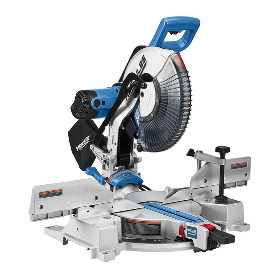
12" Dual-Bevel
Compound Miter Saw
WARNING: To prevent serious injury, User must read and
understand Owner's Manual. SAVE THIS MANUAL.
When unpacking, make sure that the product is intact and
undamaged. If any parts are missing or broken, please call
1-888-866-5797 as soon as possible. Reference 57675.
Advertisement
Table of Contents

Related Manuals for Hercules HE78


Summary of Contents for Hercules HE78
- Page 1 Owner’s Manual & Safety Instructions Model HE78 12" Dual-Bevel Compound Miter Saw WARNING: To prevent serious injury, User must read and understand Owner’s Manual. SAVE THIS MANUAL. When unpacking, make sure that the product is intact and undamaged. If any parts are missing or broken, please call...
-
Page 2: Important Safety Information
IMPORTANT SAFETY INFORMATION General Power Tool Safety Warnings 3. Personal safety a. Stay alert, watch what you are doing and Read all safety warnings, instructions, illustrations use common sense when operating a and specifications provided with this power tool. power tool. Do not use a power tool while Failure to follow all instructions listed below may you are tired or under the influence of result in electric shock, fire and/or serious injury. - Page 3 l. This product is not a toy. h. Keep handles and grasping surfaces Keep it out of reach of children. dry, clean and free from oil and grease. Slippery handles and grasping surfaces m. People with pacemakers should consult their do not allow for safe handling and control physician(s) before use.
- Page 4 f. Do not reach behind the fence with either o. Always use a clamp or a fixture designed hand closer than 100 mm (4 inches) from to properly support round material such as either side of the saw blade, to remove rods or tubing.
-
Page 5: Double Insulated Tools: Tools With Two Prong Plugs
Grounding Double Insulated Tools: Tools with Two Prong Plugs TO PREVENT ELECTRIC SHOCK AND DEATH FROM INCORRECT GROUNDING WIRE CONNECTION: Check with a qualified electrician if you are in doubt as to whether the outlet is properly grounded. Do not modify the power cord plug provided with the tool. -
Page 6: Specifications
Symbology TABLE A: RECOMMENDED MINIMUM WIRE GAUGE FOR EXTENSION CORDS* (120/240 VOLT) EXTENSION CORD NAMEPLATE Volts LENGTH AMPERES 25´ 50´ 75´ 100´ 150´ (at full load) Amperes 0 – 2.0 2.1 – 3.4 n 0 xxxx/min. No Load Revolutions per Minute (RPM) 3.5 –... - Page 7 Functions Handle Dust Lower Blade Collection Guard Blade Head Kerf Lock-Down Board Bevel Detent Scale Latch Turntable Turntable Button Miter Detent Lock Lever Miter Angle Miter Angle Miter Indicator Indicator Scale Trigger Precision Blade Guide System On/Off Switch Dust Outlet Bevel Fence Detent...
-
Page 8: Setup - Before Use
SETUP - BEFORE USE: OPERATING INSTRUCTIONS Read the ENTIRE IMPORTANT Read the ENTIRE IMPORTANT SAFETY INFORMATION section at the SAFETY INFORMATION section at the beginning of this manual including beginning of this manual including all text under subheadings therein all text under subheadings therein before set up or use of this product. -
Page 9: Setting And Testing
7. If replacing a used blade, remove the blade. 4. With the Table adjusted to the desired angle, Install the new Blade. Make sure that the Blade’s place the workpiece flush against the Fence, rotation arrow points in the same direction as secure it with the Clamp and make the cut. -
Page 10: Workpiece And Work Area Set Up
Aligning the Fence General Instructions for Use 1. After adjusting the miter or bevel setting, 1. Make sure that the Trigger is in the check and adjust both sides of the fence. off-position, then plug in the tool. 2. Loosen one of the Fence Knobs, and move its WARNING! The tool will restart automatically if stalled. -
Page 11: Maintenance And Servicing Instructions
5. If the Fence is not perpendicular (at a 90º angle) MAINTENANCE AND to the Saw Blade, loosen the four screws holding SERVICING INSTRUCTIONS the Miter Scale. Using the square to measure, move the Table and Scale together left or right until the Blade and Fence are perpendicular Procedures not specifically explained to each other, then tighten the four screws. -
Page 12: Troubleshooting
Troubleshooting Problem Possible Causes Likely Solutions Tool will not start. 1. Cord not connected. 1. Check that cord is plugged in. 2. No power at outlet. 2. Check power at outlet. If outlet is unpowered, turn off tool and check circuit breaker. If breaker is tripped, make sure circuit is right capacity for tool and circuit has no other loads. -
Page 13: Please Read The Following Carefully
PLEASE READ THE FOLLOWING CAREFULLY THE MANUFACTURER AND/OR DISTRIBUTOR HAS PROVIDED THE PARTS LIST AND ASSEMBLY DIAGRAM IN THIS MANUAL AS A REFERENCE TOOL ONLY. NEITHER THE MANUFACTURER OR DISTRIBUTOR MAKES ANY REPRESENTATION OR WARRANTY OF ANY KIND TO THE BUYER THAT HE OR SHE IS QUALIFIED TO MAKE ANY REPAIRS TO THE PRODUCT, OR THAT HE OR SHE IS QUALIFIED TO REPLACE ANY PARTS OF THE PRODUCT. -
Page 14: Parts List And Diagram
PARTS LIST AND DIAGRAM Parts List Part Description Part Description Part Description Base Head Lock-Down Pin Set 145 Torsion Spring Wrench Clamp Head Lock-Down Pin 146 Top Pivot Bolt O Ring Wrench Wear Plate Table Upper Guard 149 Synchronous Pulley Cover Linear Bearing Bottom Pivot Bolt Shaft Set... -
Page 15: Assembly Diagram
Assembly Diagram Item 57675 For technical questions, please call 1-888-866-5797. Page 15... -
Page 16: Limited 90-Day Warranty
LIMITED 90 DAY WARRANTY Harbor Freight Tools Co. makes every effort to assure that its products meet high quality and durability standards, and warrants to the original purchaser that this product is free from defects in materials and workmanship for the period of 90 days from the date of purchase.
Need help?
Do you have a question about the HE78 and is the answer not in the manual?
Questions and answers
how to change saw blade
To change the saw blade on a Hercules HE78:
1. Unplug the tool from its power source.
2. Pull out the Head Lock-Down Pin and raise the Saw Head to the upper position.
3. Raise the Lower Blade Guard out of the way and hold it up.
4. Loosen the Guard Plate Bolt and swing the Guard Plate up and out of the way.
5. If replacing a used blade, remove the blade.
6. Install the new blade, ensuring the blade’s rotation arrow matches the arrow on the Lower Blade Guard.
7. Replace the Outer Flange and Arbor Bolt. Position the cupped side of the Flange against the blade.
8. Hold in the Spindle Lock while tightening the Arbor Bolt.
This answer is automatically generated