Table of Contents
Advertisement
Owner's Manual &
Safety Instructions
19f
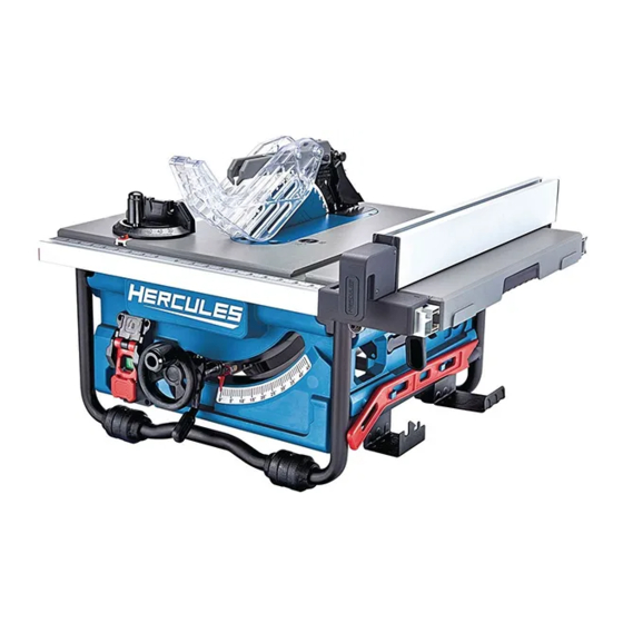
10" COMPACT JOBSITE TABLE SAW
WARNING: To prevent serious injury, user must read and
understand Owner's Manual. SAVE THIS MANUAL.
When unpacking, make sure that the product is intact and
undamaged. If any parts are missing or broken, please call
1-888-866-5797 as soon as possible. Reference 64855
Advertisement
Table of Contents

Related Manuals for Hercules HE76


Summary of Contents for Hercules HE76
- Page 1 Owner’s Manual & Safety Instructions 10″ COMPACT JOBSITE TABLE SAW WARNING: To prevent serious injury, user must read and understand Owner’s Manual. SAVE THIS MANUAL. When unpacking, make sure that the product is intact and undamaged. If any parts are missing or broken, please call 1-888-866-5797 as soon as possible.
-
Page 2: Important Safety Information
IMPORTANT SAFETY INFORMATION 3. Personal safety a. Stay alert, watch what you are doing and Read all safety warnings and all instructions. use common sense when operating a Failure to follow the warnings and instructions may result power tool. Do not use a power tool while in electric shock, fire and/or serious injury. - Page 3 m. People with pacemakers should consult their h. Keep handles and grasping surfaces physician(s) before use. Electromagnetic fields in dry, clean and free from oil and grease. close proximity to heart pacemaker could cause Slippery handles and grasping surfaces pacemaker interference or pacemaker failure. do not allow for safe handling and control In addition, people with pacemakers should: of the tool in unexpected situations.
- Page 4 7. Cutting procedures warnings k. Do not remove pieces of cut-off material while the saw is running. The material may become DANGER: Never place your fingers or trapped between the fence or inside the saw blade hands In the vicinity or in line with the guard and the saw blade pulling your fingers into saw blade.
-
Page 5: Grounded Tools: Tools With Three Prong Plugs
h. Use extra caution when cutting a workpiece h. Never use damaged or incorrect saw blade that is twisted, knotted, warped or does mounting means such as flanges, saw blade not have a straight edge to guide it with a washers, bolts or nuts. -
Page 6: Double Insulated Tools: Tools With Two Prong Plugs
Double Insulated Tools: Tools TABLE A: RECOMMENDED MINIMUM WIRE GAUGE FOR EXTENSION CORDS* (120/240 VOLT) with Two Prong Plugs EXTENSION CORD NAMEPLATE LENGTH AMPERES 25´ 50´ 75´ 100´ 150´ (at full load) 0 – 2.0 2.1 – 3.4 3.5 – 5.0 5.1 –... -
Page 7: Setup - Before Use
SETUP - BEFORE USE TO PREVENT SERIOUS INJURY FROM ACCIDENTAL OPERATION: Turn the Power Switch of the tool off and unplug the tool from its electrical outlet before performing any procedure in this section. Note: For additional information regarding the parts listed in the following pages, refer to the Assembly Diagram near the end of this manual. - Page 8 Assembly Removing the Table Insert 1. Lower the blade by turning the Height Attaching the Handwheel Adjustment Knob counter-clockwise. 1. Remove Handwheel from its storage box located underneath the Table Saw. Storage 2. Remove tape and Set Screw from Handwheel. 3.
-
Page 9: Adjusting Riving Knife
Adjusting Riving Knife Removing and Installing the Blade Note: Riving Knife has three mounting holes for three NOTICE: To work properly, the saw blade teeth positions. The uppermost position is for all through must point down toward the front of the saw. Failure cuts. -
Page 10: Installing The Blade Guard
5. To install the blade, place new saw blade onto Note: Pull up on Pawls assembly to make the Inner Blade Flange of the tool arbor. sure it is secured to Riving Knife. WARNING! When installing the saw blade, WARNING! Use extra caution when cutting make sure that the saw blade teeth point wood with slippery surface as the anti-kickback down at the front side of blade. -
Page 11: Operation
Installing the Miter Gauge OPERATION Note: The Miter Gauge can be installed in either Read the ENTIRE IMPORTANT miter gauge groove on either side of blade. SAFETY INFORMATION section at the Slide the Miter Gauge into one of the guide grooves. beginning of this manual including all text under subheadings therein Miter Gauge... -
Page 12: Rip Fence Operation
Lock Knob Miter Gauge Bevel Lock Handle 3. Tighten Lock Knob by turning it clockwise. Height/bevel Adjustment Handwheel Using the Extension Table 5. Make sure blade is at desired angle. Tighten Bevel Lock Handle clockwise. 1. Set the Rip Fence on the Extension Table. 2. - Page 13 1. Adjust the miter gauge to the needed General Operating Instructions angle and place it in the left or right miter gauge groove on the working table. Placement of Hands during Cutting Process 2. Hold the workpiece against the miter gauge, 1.
-
Page 14: Maintenance And Servicing
Cleaning, Maintenance, MAINTENANCE AND SERVICING and Lubrication Procedures not specifically explained 1. BEFORE EACH USE, inspect the general in this manual must be performed condition of the tool. Check for: only by a qualified technician. • loose hardware • misalignment or binding of moving parts •... -
Page 15: Please Read The Following Carefully
PLEASE READ THE FOLLOWING CAREFULLY THE MANUFACTURER AND/OR DISTRIBUTOR HAS PROVIDED THE PARTS LIST AND ASSEMBLY DIAGRAM IN THIS MANUAL AS A REFERENCE TOOL ONLY. NEITHER THE MANUFACTURER OR DISTRIBUTOR MAKES ANY REPRESENTATION OR WARRANTY OF ANY KIND TO THE BUYER THAT HE OR SHE IS QUALIFIED TO MAKE ANY REPAIRS TO THE PRODUCT, OR THAT HE OR SHE IS QUALIFIED TO REPLACE ANY PARTS OF THE PRODUCT. -
Page 16: Parts List And Diagram
PARTS LIST AND DIAGRAM Parts List Part Description Part Description Frame Hex socket head cap screw Spring pad Fixed foot Flat pad Hex socket head cap screw Body Adjustable foot Lifting lever Compressed spring Cross recessed pan head screw Foot adjustment post Cross recessed pan head screw Cross-recessed pan Lifting guide column... - Page 17 Parts List (cont’d) Part Description Part Description Bearing Scale sign Extension plate Front ruler Lower protection baffle Pin knob Sub-table locking plate Ring Table Locking Rod Washer Pressure card Pawl Slider Pawl Cylindrical pin 4 × 16 Stop leaf spring Cover screw Stop sheet support seat Open pin...
- Page 18 Parts List (cont’d) Part Description Part Description Guard plate locking plate Lock plate Stop plate Guide divider Non-stop sheet Guide tube screw Right Guard Guide tube Guide the tube to press the handle Guide tube after the fixed seat Guide pin Locking block Sliding pin Guide tube wheel...
-
Page 19: Assembly Diagram
Assembly Diagram Item 64855 For technical questions, please call 1-888-866-5797. Page 19... -
Page 20: Limited 90-Day Warranty
LIMITED 90 DAY WARRANTY Harbor Freight Tools Co. makes every effort to assure that its products meet high quality and durability standards, and warrants to the original purchaser that this product is free from defects in materials and workmanship for the period of 90 days from the date of purchase.
Need help?
Do you have a question about the HE76 and is the answer not in the manual?
Questions and answers
Need power cord and fence for HE76
The power cable for the Hercules HE76 is listed as item 38 in the manual. The fence is referred to as the Rip Fence, which has a lock lever for adjustments.
This answer is automatically generated
Do you sell the electric motor as one complete unit