
Related Manuals for Ampac LoopSense EN54

Summary of Contents for Ampac LoopSense EN54
- Page 1 SMART TERMINAL LOOPSENSE EN54 INSTALLATION &COMMISSIONING SmartTerminal Smart Terminal LoopSense EN54 Installation, Commissioning & Operation MAN 1557-6...
-
Page 2: Table Of Contents
SMART TERMINAL LOOPSENSE EN54 INSTALLATION &COMMISSIONING Table of Contents Page No. Introduction ..........................3 Mechanical ..........................4 Mounting the Enclosure ....................4 2.1.1 Enclosure Details..................4 2.1.2 Fixing the Chassis to the Wall ..............4 2.1.3 Board Removal / Replacement ..............5 2.1.4... -
Page 3: Introduction
SMART TERMINAL LOOPSENSE EN54 INSTALLATION &COMMISSIONING Introduction SmartTerminal has been designed for use with the LoopSense series of FACP’s. 4 line by 40 character LCD with backlight and navigation keys keys allow the SmartTerminal to be used for FACP operation and interrogation. Note the backlight is only... -
Page 4: Mechanical
SMART TERMINAL LOOPSENSE EN54 INSTALLATION &COMMISSIONING Mechanical SmartTerminal is supplied in an ABS cabinet and consists of; The Main Card, with all controls and indicators mounted directly onto it 1 X Termination Board 2 X ABS door keys ... -
Page 5: Board Removal / Replacement
SMART TERMINAL LOOPSENSE EN54 INSTALLATION &COMMISSIONING 2.1.3 Board Removal / Replacement If a PCB has to be removed the following precautions should be observed; Removing the door will provide better access to the boards and will ensure the hinges are not accidentally stressed. -
Page 6: Removing The Knockouts
SMART TERMINAL LOOPSENSE EN54 INSTALLATION &COMMISSIONING 2.1.4 Removing the Knockouts The knock-outs should be removed with a sharp tap in the rim of the knock-out using a flat broad- bladed screwdriver. Note: Use of excessive force could damage the enclosure around the knock-out. -
Page 7: Installation & Cabling
SMART TERMINAL LOOPSENSE EN54 INSTALLATION &COMMISSIONING Installation & Cabling The SmartTerminal is then connected to the FACP as shown below. SHIELDED COMMS CABLE +24VDC SHIELD COMMS AUX OUT1 INPUTS LOOP 1 LOOP 2 MONITORED O/PS RELAY 1 RELAY 2 RELAY 3... -
Page 8: Setting The Address
SMART TERMINAL LOOPSENSE EN54 INSTALLATION &COMMISSIONING Setting the Address PRINTER PARALLEL SERIAL LCD BL C N 1 BRD82ZICC4- C N 3 22/09/2009 C N 2 N1236 C N 4 BUZZER SILENCE FAULT BUZZER RN10 SW27 CONFIG RN11 RN12 DIAGNOSTIC /... -
Page 9: Setting The Smartterminal In Loopmaster
SMART TERMINAL LOOPSENSE EN54 INSTALLATION &COMMISSIONING Setting the SmartTerminal in LoopMaster This section assumes the engineer has experience in the use of LoopMaster and hence has an understanding of it operation. To commence the programming go to the “Tree View” within LoopMaster as shown below. - Page 10 SMART TERMINAL LOOPSENSE EN54 INSTALLATION &COMMISSIONING The List View Figure 8 The SmartTerminal add on List View appears immediately below the SmartTerminal add on Details View and consists of a summary of all available SmartTerminal add ons assigned to the current panel.
-
Page 11: Operation
SMART TERMINAL LOOPSENSE EN54 INSTALLATION &COMMISSIONING Operation The operation of SmartTerminal can be considered to be in one of three states, these are; 1. Power up - when the SmartTerminal is initialising 2. Normal - when the SmartTerminal address has been set and is communicating with the... -
Page 12: Controls And Indicators
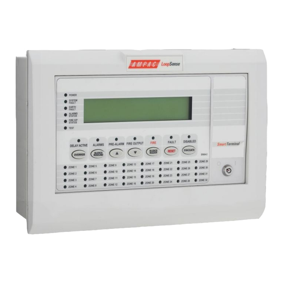
SMART TERMINAL LOOPSENSE EN54 INSTALLATION &COMMISSIONING Controls and Indicators All controls, except for the Enable / Disable keyswitch, are of a momentary push button style. Figure 10: SmartTerminal Front Panel Layout KEYSWITCH Access levels There are two levels of access. - Page 13 SMART TERMINAL LOOPSENSE EN54 INSTALLATION &COMMISSIONING (Yellow) The LED is illuminated when the sounders have been silenced in response to a FIRE condition, indicating the resound function is active. Silence / Resound Press to silence the alarm devices (associated LED illuminated).
- Page 14 SMART TERMINAL LOOPSENSE EN54 INSTALLATION &COMMISSIONING (Red) The LED is illuminated when one or more devices are reporting a FIRE condition and are not disabled. Silence Buzzer Silences the panel buzzer. Buzzer is activated under the following conditions: Alarm condition ...
- Page 15 SMART TERMINAL LOOPSENSE EN54 INSTALLATION &COMMISSIONING (Yellow) The LED is illuminated when one or more zone detectors, loop devices or panel outputs are disabled. Evacuate Turns on all alarm devices (visual and aural) outputs and activates the Fire indicator. The SILENCE / RESOUND or RESET control shall turn off all alarm devices (visual and aural).
-
Page 16: Lcd Screen Format
SMART TERMINAL LOOPSENSE EN54 INSTALLATION &COMMISSIONING LCD Screen Format There are 3 events that can be reported and displayed by SmartTerminal. The types of event are; Fire Faults and Disables. The types of events are only associated with sensors and detectors hence faults associated with modules, loops O/C –... - Page 17 SMART TERMINAL LOOPSENSE EN54 INSTALLATION &COMMISSIONING Normal / Default: The format for reporting that everything is normal is: <DATE> <TIME> ACCESS LEVEL: 1 <USER DESCRIPTOR LINE 1> <USER DESCRIPTOR LINE 2> <SYSTEM STATUS> <DAY MODE-MAN I/O> The screen is only displayed when there are no alarms, fault or disables on the panel.
-
Page 18: Specifications
SMART TERMINAL LOOPSENSE EN54 INSTALLATION &COMMISSIONING Specifications MECHANICAL Dimensions ABS Cabinet BX05: (mm) 195mm (H) x 345mm (W) x 50mm (D) Dimensions ABS Cabinet BX1: (mm) 300mm (H) x 360mm (W) x 100mm (D) ENVIROMENTAL Temperature: -5ºC to + 55ºC... -
Page 19: Trouble Shooting Chart
Check the SmartTerminal Diagnostic Config LED is flashing. If not the FACP is not communicating with the SmartTerminal. Check the RS485 cabling. If flashing check the SmartTerminal’s address. UNCONTROLLED DOCUMENT NOTE: Due to AMPAC’s commitment to continuous improvement specifications may change without notice.
Need help?
Do you have a question about the LoopSense EN54 and is the answer not in the manual?
Questions and answers