Advertisement
Quick Links
This Quick Start Guide provides a general overview for basic installation. For more in-depth information and troubleshooting steps, please refer to the full Operator's Guide for your meter.
INSTALLATION OVERVIEW - DIN RAIL MOUNT ENCLOSURE*
1
1.
Attach DIN Rail
Attach a section of T35 DIN rail within a suitable UL-approved
enclosure.
▪
Leave enough clearance for voltage, CT, and
communications wires to be routed within enclosure.
▪
UL-approved enclosure is customer supplied.
35mm
T35 DIN Rail
4
4.
Re-attach HV Cover
Meter is IP30 (TouchSāf™) with internal cover installed.
*For an installation overview of the Wall Mount Enclosure, see the full Operator's Guide.
WIRING
HIGH VOLTAGE MAY BE PRESENT. RISK OF ELECTRIC SHOCK. LIFE THREATENING
VOLTAGE MAY BE PRESENT. QUALIFIED PERSONNEL ONLY.
i
These diagrams show the wiring confi guration for the Service Types available in the
Service drop-down list under "Meter Setup; Service " in ViewPoint HD Software.
The PowerScout HD Meter is internally powered through
i
the voltage between L1 and L2. For Single Phase
installations, where no L2 exists, connect a jumper from N
to L2. This connection provides power to the meter while
maintaining Neutral as the metering voltage reference.
The PowerScout HD Meter uses the Neutral terminal as a voltage reference. For
i
systems without a neutral conductor, connect a wire from the N terminal to ground.
CONNECTING VOLTAGE WIRING AND CTs TO THE METER
This image below represent CT and voltage connections between the PowerScout 3 HD and
the common service types. For specifi c wiring questions outside the scope of this document,
contact DENT technical support.
4-WIRE, 3-PHASE WYE
3-WIRE, 3-PHASE DELTA
© DENT Instruments, Inc.
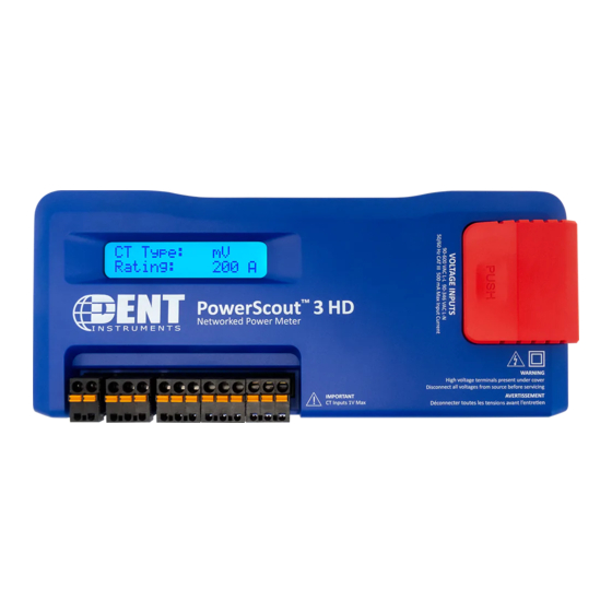
PowerScout™ 3 HD
Single-Circuit Power Meter
Quick Start Guide
FOR QUALIFIED PERSONNEL ONLY
2
2.
Mount
Press the top edge of the meter's DIN rail channel to
the DIN rail itself. Then push the meter fi rmly towards
the DIN rail until it clicks into place.
DIN Rail
Channel
T35 DIN Rail
DIN Rail Tabs
Pull tabs with screwdriver to release.
5
5.
Connect CT & Communications
Use only 333.3mV (1/3 V) output CTs or DENT RōCoils.
CT Connections (x3)
RS-485
Bare (RŌCoil) (S)
Black or Brown (-)
White (+)
EXAMPLE 1
Wiring the PowerScout in a 3-Wire, Split Phase Service Panel
TYPICAL LOADS:
Single Phase L1-N or L2-N 110 VAC: Lighting, Appliance, or Living Zone
Single Phase L1-L2 220 VAC: Water Heater or Equipment with no Neutral wire.
Split Phase L1-L2 220 VAC: Service Entrance, Dryers, or Equipment with Neutral wire.
3-Wire, 1-Phase
used on MAINS
RōCoil CTs Shown
L1
L2
L3
N
110 VAC Plug Loads
Split Core CTs Shown
EXAMPLE 2
Wiring the PowerScout in a 4-Wire, 3-Phase Service Panel
4-Wire, 3-Phase
Mains Monitoring
L1-N, L2-N, L3-N
RōCoil CTs Shown
4-Wire, 3-Phase
Neutral Current
L1-N, L2-N, L3-N
■
www.DENTinstruments.com
■
3
3.
Remove HV Cover
Remove the TouchSāf™ high voltage cover and connect
voltage leads to the meter
WARNING: RISK OF ELECTRIC SHOCK. DO NOT
ENERGIZE METER WITH VOLTAGE COVER REMOVED.
FOLLOW ALL STATE AND FEDERAL ELECTRICAL
CODES.
▪ Using 14 AWG THHN, 600VAC rated wire, connect the
voltage leads (L1, L2, L3, and N) as necessary to the
meter through a dedicated disconnect or circuit breaker.
DO NOT EXCEED 346V L-N or 600V L-L.
▪ Mark the circuit breaker as "PowerScout Meter"
USB-C
Ethernet
L1-N, L2-N
Single Phase
L1-N or L2-N
Single Phase
Branch Load
L1-N
WYE Load with
1.800.388.0770 ■
support@DENTinstruments.com
Rev062320
TouchSāf High Voltage Cover
Connect the Neutral
wire to VIN 1, N
terminal on the
PSHD Meter
Meter is powered
from L1 to L2 on the
VIN 1 connector
Label as Meter
Disconnect
METER DISCONNECT
Single Phase
220 VAC Load
L1-L2
3-Wire, 1-Phase
Split Load
L1-N, L2-N
Connect the Neutral
Wire to the VIN 1
Neutral Terminal on
the PSHD Meter
Meter Power
METER DISCONNECT
Connect All Phases to
the VIN 1 Terminals
Label as Meter
Disconnect
3-Wire, 3-Phase
DELTA Load
No Possibility of
Neutral Current
Two CTs on L1 and L3
Advertisement

Related Manuals for DENT Instruments PowerScout 3 HD


Summary of Contents for DENT Instruments PowerScout 3 HD
- Page 1 Single Phase Split Core CTs Shown 220 VAC Load This image below represent CT and voltage connections between the PowerScout 3 HD and L1-L2 the common service types. For specifi c wiring questions outside the scope of this document, contact DENT technical support.
- Page 2 USB-C POWERSCOUT 3 HD METER ANATOMY The PowerScout 3 HD is available in two confi gurations. The DIN-Rail Mount Enclosure is to be mounted in a UL-approved electrical enclosure while the Wall Mount Enclosure is ready to be mounted on the wall next to an electrical panel and does not require an additional enclosure.
Need help?
Do you have a question about the PowerScout 3 HD and is the answer not in the manual?
Questions and answers