
Related Manuals for DENT Instruments powerscout 3037


Summary of Contents for DENT Instruments powerscout 3037
- Page 1 Operator’s Guide ™ PowerScout 3037 Power Meter Includes: ViewPoint™ 4.0 Software March 12, 2015 GlobalTestSupply www. .com Find Quality Products Online at: sales@GlobalTestSupply.com...
- Page 2 Operator’s Guide: PowerScout™ Power Meters ©2015 DENT Instruments, Inc. All rights reserved. This manual may not be reproduced or distributed without written permission from DENT Instruments. PowerScout™, ViewPoint™, and PhaseChek™ are trademarks of DENT Instruments, Inc. Windows®, Windows® Vista, Windows® 7, Windows® 8, Windows® XP, and Notepad® are registered trademarks of Microsoft Corporation.
-
Page 3: Table Of Contents
........................37 IELD NSTALLATION Mounting a PowerScout 3037 ....................... 37 Wiring Connections on the PowerScout 3037 ..................38 Completing the Field Installation ......................39 Using the Pulse Output Port Function ....................39 Modbus Output Port Registers ........................40 BACnet Output Port Objects ..........................40 GlobalTestSupply www. - Page 4 Connecting RōCoil CTs to a Load ........................43 CT Wire Lead Polarity ............................45 Connecting Voltage ..........................45 Powering the Meter ............................46 PowerScout Single-Phase Connections ......................46 PowerScout 3037 Wiring Diagrams ....................... 48 Three-wire Delta ..............................48 Four-wire Wye ..............................49 Two-wire Single Phase .............................50 Three-wire Single Phase ...........................51 Verifying Installation with PhaseChek ....................
-
Page 5: Powerscout 3037 Serial/ Powerscout 3037 Ethernet
..........................88 PPENDICES Appendix A—Additional Wiring Diagrams ..................... 88 2-CT, 3-Wire Delta ............................89 3-Phase Delta with a “Wild” Leg ........................90 Appendix B—Connecting Multiple PowerScouts to an RS-485 Network ..........91 Communication Protocol ..........................91 Daisy Chain Layout for RS-485 Network ......................91 Networking Using the BACnet MS/TP/Modbus RTU Protocol .................91 Appendix C—Firmware Updates ...................... -
Page 6: Introduction
You may connect as many Ethernet units as equal to the amount of available IP Addresses. There is a configurable digital pulse output port on the PowerScout 3037 that can be used to output kWh, kVARh, or kVAh pulses to external devices, or to toggle on and off to control a remote device or relay. - Page 7 Example of a COC for a PowerScout 3037 GlobalTestSupply www. .com Find Quality Products Online at: sales@GlobalTestSupply.com...
-
Page 8: Meter Anatomy
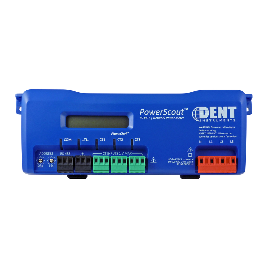
Meter Anatomy GlobalTestSupply www. .com Find Quality Products Online at: sales@GlobalTestSupply.com... -
Page 9: Powerscout™ Meter Safety Summary And Specifications
PowerScout™ Meter Safety Summary and Specifications These items conform to the following: This general safety information is to be used by both the Logger operator and servicing personnel. DENT PS3037-S-N/PS3037-S-D/PS3037-E-N/ Instruments, Inc. assumes no liability PS3037 Series: PS3037-E-D for user’s failure to comply with these Conforms to UL Std 61010-1, 3rd safety guidelines. - Page 10 PowerScout 3037 is also capable of measuring DC voltages up to 600 VDC with the following caveats. 1) The internal fuse installed in the PowerScout 3037 is not a suitable disconnect for voltages above 80 VDC. Customers using the PowerScout 3037 for high voltage DC systems must install a UL listed inline 600 volt DC fuse with a rating of 1 amp or less.
- Page 11 Battery Life: (If equipped) The lithium battery is only used to maintain the date and clock settings during power failure and has a life expectancy of greater than 10 years. Contact DENT Instruments for service. No accessories are approved for use with the PowerScout other than those specified in the DENT Instruments product literature and price sheets.
-
Page 12: Powerscout™ Résumé De Sécurité Et Spécifications
PowerScout™ Résumé de Sécurité et Spécifications Tous les articles sont conformes à ce qui suit: Cette information de sécurité est destinée à être utilisée à la fois par l'opérateur de l'enregistreur PS3037-S-N/PS3037-S-D/PS3037-E-N/ et le personnel de service. DENT PS3037-E-D Instruments, Inc n'assume aucune PS3037 Série: responsabilité... - Page 13 TENSIONS C. C. La PowerScout 3037 est conçu pour mesurer tensions c. a. pour les installations jusqu'à 600 V c. a. Le PowerScout 3037 est également capable de mesurer les tensions c. c. jusqu'à 600 V c. c. avec les avertissements suivants.
-
Page 14: Powerscout 3037 Technical Specifications
PowerScout 3037 Technical Specifications Specification Description Service Types Single Phase, Three Phase-Four Wire (WYE), Three Phase-Three Wire (Delta) 3 Voltage Channels 80-346 Volts AC Line-to-Neutral, 600V Line-to-Line, CAT III 3 channels, 0.525 VAC max, 333 mV CTs, 0-4,000+ Amps depending on current... - Page 15 Mechanical Operating Temperature -7 to + 60⁰ C (-20 to 140⁰ F) Humidity 5% to 95% non-condensing Enclosure ABS plastic, 94-V0 flammability rating Weight 340 g (12 ounces), exclusive of CTs Dimensions 24.2 x 8.5 x 4.0 cm (9.5” x 3.3” x 1.6”) Accessories Mounting Rail Compatible with a TS35/7 DIN Rail Channel...
-
Page 16: Prepping For Field Installation
The ViewPoint software is designed to let you easily configure the PowerScout for different current transformers, check readings, and verify correct setup. All of DENT Instruments PowerScout meters use ViewPoint software to communicate with the meter. It needs to be installed on any computer talking to the PowerScout 3037. -
Page 17: Connecting A Communication Cable
IP address is required. The screen display changes based on your connection selection. USB connector on the PowerScout 3037 can be used to power the unit when configuring it using ViewPoint and Modbus protocols. If connecting with a USB cable is not practical, the use of an RS-485 to USB adapter connected to your PC may be used for communicating with your PowerScout. - Page 18 ? If an RS-485 adapter is used instead of a USB, an RS-485 driver must be installed on your computer and power applied to the PowerScout meter before the software will function properly. Installing the RS-485 Adapter on a Computer NOTE: If ViewPoint was installed first, it needs to be restarted following an RS-485 driver installation.
- Page 19 RS-485 adapter are set to RS-485, Echo Off, 2 Wire, 2 Wire as shown in Figure II-2 before plugging the adapter into the PowerScout 3037. Figure II-2: Dip switches on back of RS-485...
- Page 20 NOTE: USB is always active on the PS3037 (and the protocol is Modbus over the USB virtual communications port). NOTE: If ViewPoint was installed first, it needs to be restarted following a RS-485 driver installation. If a RS-485 port does not appear in the drop-down list, the RS-485 was not installed correctly. 1) Select USB/RS-485 (MSTP) as your communication type.
- Page 21 Setting the Network Address Switches There are two rotary network address switches on a serial PowerScout 3037, labeled MSB and LSB. These two switches are used to select the BACnet/Modbus address the client uses to communicate with the PowerScout. The rotary switches are 16-position, hexadecimal switches. The default factory setting is hex 01. The address is a hexadecimal (hex) value, represented by the digits 0 through 9 and letters A through F.
-
Page 22: Connecting And Communicating Via An Ethernet (Tcp/Ip) Connection
The meter will require power to communicate over Ethernet. Power can be supplied by connecting the USB or voltage lines 1 and 2. PowerScout 3037 Keep in mind that the Ethernet connection must have an IP Address in the ViewPoint software that can... - Page 23 1) Select Ethernet (TCP/IP) to gather information via a network connection. When selected, the Communications Setup screen changes and an IP Address is required as address switches are ignored. 2) Select your mode of communication. 3) Enter the IP Address for the Ethernet connection of the meter or select one of the previously used addresses from the drop-down list.
- Page 24 always assign the same IP number back to the meter. This option may also require a network administrator. The Scan Network button scans the network for possible meters and displays them in the Logger Selection dialog box. Look for the serial number on the meter (found on the back of the meter) to determine which connection point is yours.
-
Page 25: Communications Leds
Communications LEDs The PowerScout COM LEDs signal the following communication information. PS3037 S ERIAL BACnet Modbus Description Steady Green Steady Green Power is applied to the meter. Flashing Green Flashing Green The meter is communicating. Steady Red Communications failure, or talking with BACnet while the meter is in Modbus mode. -
Page 26: Meter Setup
Meter Setup Once communications is established between the PC and the PowerScout, you are now ready to configure the meter for the field. This is accomplished in the Meter Setup tab of ViewPoint. The Meter Setup screen allows unique changes to an element on the 3037. Within the element, CT Phase, Type, Amps, and Phase Shift are entered, based on wiring connection, for CT1, CT2, and CT3. -
Page 27: Entering Wiring Information For An Element
1) Select WYE, DELTA, or Single Phase as the wiring connection. NOTE: DENT Instruments recommends using 3 CTs in a WYE connection for Delta loads. A WYE connection automatically displays all three CTs. Any changes made to CT1 also apply to ... - Page 28 Current Transformers Recommended CT Phase Shift Values Split Core CT-SCM-0100 1.75° Medium CT-SCM-0200 1.50° CT-SCM-0400 1.30° CT-SCM-0600 1.30° Split Core Large CT-SCL-0600 0.00° CT-SCL-1000 0.00° Split Core High CT‐SHS‐0005 0.50° Accuracy Hinge Mini 20A 0.75° Mini 50A 0.75° MIDI 100A 0.12°...
-
Page 29: Selecting A Scalar
ELECTING A CALAR : The The use of Modbus protocols limits the data registers to a maximum of two register value must bytes (16 bits) or a maximum decimal value of 65535. Modbus requires that be less than 65,535. the data be unsigned (positive) integer values. To overcome these limitations some measured (and stored) values must be scaled to fit into the Modbus registers. - Page 30 The following table is an example when selecting a data scalar for 3-phase loads based on the CT size or maximum current. These are the minimum recommended scalar settings. 3-phase Loads CT Size or Max. Current 230 volts 460 volts Scalar 1 Scalar 2 Scalar 2...
-
Page 31: Comms Setup
Values Requiring Two Registers Additionally, some values (e.g., kilowatt hours) may cover a dynamic range that is larger than 65535 and require two Modbus registers. Any parameter in the Modbus Register Assignment tables that shows two registers (identified by the terms MSW (Most Significant Word) and LSW (Least Significant Word)) are examples of this wide-ranging parameter. -
Page 32: Settings
RS-485 S ETTINGS Change the Data Bits or Baud Rate on the meter by using these fields. EVICE ETTINGS Enter a new value into any field and click Send Setup to Meter to update the Device ID (meter identification), Max Master (# of units on network), or MAX Info Frames (# of packets sent via MS/TP). THERNET ETTINGS Connecting the Ports... -
Page 33: Establishing Communication Protocol
Establishing Communication Protocol The PowerScout communicates using the BACnet MS/TP or Modbus RTU protocols via the RS-485/Ethernet interface. To establish communication with a RS-485, the settings must meet the following requirements: The Modbus/BACnet address on the PowerScout and in the ViewPoint software must be set to ... - Page 34 Changing the PowerScout from Modbus to BACnet mode: 1) Connect to the PowerScout using ViewPoint. 2) Go to the Read/Write Registers tab in ViewPoint. 3) Enter 44612 into the Register field or click List to select from the Register Picker List. 4) In the Value field, enter 1833 to change to BACnet mode.
- Page 35 Green *Factory Default After powering up the PowerScout 3037, you will have 10 seconds to make changes. However, every time a rotary switch is changed, the 10 second timer resets. After 10 seconds of no switch action, the settings take effect and the switches revert to the Modbus Address selector if in Modbus mode or MAC address if in BACnet mode.
-
Page 36: Field Installation
PowerScout meters must be installed in an approved electrical panel or enclosure using proper installation practices according to the local electrical codes. To mount the PowerScout 3037, use the two tabs provided at both ends of the case. Securely ... -
Page 37: Wiring Connections On The Powerscout 3037
The PowerScout 3037 can also be mounted on a 35 mm width DIN rail. Top hat rail EN 50022 Wiring Connections on the PowerScout 3037 High voltage MAY BE PRESENT. Risk of electric shock. Life threatening voltages may be present. -
Page 38: Completing The Field Installation
Pulse output is used to generate pulses for external devices such as data loggers that can accept pulses but do not have BACnet or Modbus capability. The PowerScout 3037 can generate pulses based on accumulated value(s) such as system kWh, system kVARh, and system kVAh. When a pulse is generated by the meter, the pulse LED will briefly flash, otherwise it will remain dark. -
Page 39: Modbus Output Port Registers
For system pulse output: kWh pulse output—write 44001 into the pulse output configuration object. kVAh pulse output—write 44011 into the pulse output configuration object. kVARh pulse output—write 44008 into the pulse output configuration object. ODBUS UTPUT EGISTERS Modbus Offset Register Name... -
Page 40: Wiring Cts
Wiring CTs 1) Insert the CT wires into the connector/s. See the following CT Type Wiring Connections table for the correct wiring configuration. CT Type Wiring Connections Split-Core *2 wire (+, –) RōCoil *3-wire (+, –, shield) 1) Attach the CTs onto the PowerScout connections labeled CT 1, CT 2 and CT 3. 2) Place the CTs on the phase wires of the load to be monitored and corresponding to the phase of the voltage leads. -
Page 41: Connecting Split-Core Style Millivolt Cts To A Load
ONNECTING PLIT TYLE ILLIVOLT S TO A 1) Open the CT by holding on to the removable leg and pulling it apart. 2) Connect CT around the load conductor to be measured. Make sure the maximum current of the conductor does not exceed the maximum CT rating listed on the CT data sheet. 3) Carefully re-connect the removable leg while ensuring the CT core alignment matches. -
Page 42: Connecting Rōcoil Cts To A Load
5) Connect the white wire on the CT to the positive terminal on the measuring device. 6) Connect the black wire on the CT to the negative terminal on the measuring device. ? Correct orientation of a CT is required to ensure proper measurement. If an arrow is shown on the CT label, it should be pointed toward the load. - Page 43 Positive Negative Shield Connecting RōCoil CTs PowerScout 3037 w/RōCoil CTs attached to load GlobalTestSupply www. .com Find Quality Products Online at: sales@GlobalTestSupply.com...
-
Page 44: Ct Wire Lead Polarity
CT W OLARITY CT Type CT Lead + CT Lead - Rogowski (RōCoil)* White Brown Split Core mV White Black Clamp On mV Black Table III-4: CT Polarity NOTE: The directionality for Rogowski CTs is the arrow points toward the load (e.g. motor). * RōCoils have a shield wire which must be connected to the meter. -
Page 45: Powering The Meter
OWERING THE ETER Connect the PowerScout meter 14 AWG THHN Minimum 600VAC rating (or equivalent in order to maintain 600VAC safety rating of the device) voltage leads as close as possible to a building-installed, dedicated circuit disconnect breaker. Mark the breaker as the “disconnect”... - Page 46 A Typical 115V Single-Phase Panel Setup Connect the Black L1 voltage lead to Voltage L1 (hot), Red L2 voltage lead to Neutral, and White N voltage lead to neutral. CT1 would monitor the L1 load. CT3 can be used if the Blue L3 voltage lead is connected to L1.
-
Page 47: Powerscout 3037 Wiring Diagrams
WIRE ELTA Use a Service Type 0 (zero) value for BACnet Object 12080 or a 0 (zero) value for Modbus Register 44607 on this wire configuration. DENT Instruments recommends using the 3 CT Method (WYE) for delta loads. GlobalTestSupply www. -
Page 48: Four-Wire Wye
WIRE Use a Service Type 0 (zero) value for BACnet Object 12080 or a 0 (zero) value for Modbus Register 44607 on this wire configuration. GlobalTestSupply www. .com Find Quality Products Online at: sales@GlobalTestSupply.com... -
Page 49: Two-Wire Single Phase
WIRE INGLE HASE Use a Service Type 0 (zero) value for BACnet Object 12080 or a 0 (zero) value for Modbus Register 44607 on this wire configuration. GlobalTestSupply www. .com Find Quality Products Online at: sales@GlobalTestSupply.com... -
Page 50: Three-Wire Single Phase
HREE WIRE INGLE HASE Use a Service Type 0 (zero) value for BACnet Object 12080 or a 0 (zero) value for Modbus Register 44607 on this wire configuration. GlobalTestSupply www. .com Find Quality Products Online at: sales@GlobalTestSupply.com... -
Page 51: Verifying Installation With Phasechek
CT orientation and avoiding faulty data collection. Verifying the PowerScout Meter Setup Using the LEDs The PowerScout 3037 uses three bi-color PhaseChek LEDs. These LEDs provide the following information: All LEDs are green—the system power factor is greater than 0.55 and the CTs are properly ... - Page 52 Error Description Correction CT 2 and CT 3 are reversed. Switch the position of the CTs flashing red. CT 1 and CT 2 are reversed. Switch the position of the CTs flashing red. Switch CT 1 with CT 2. ...
-
Page 53: Verifying Installation With The Viewpoint Software
Verifying Installation with the ViewPoint Software In addition to verifying your connections with PhaseChek, you can also use the ViewPoint software to check connections. Any computer running ViewPoint software, whether a laptop connected directly to the meter, a smart phone, or a PC connected to the network can bring up the software and learn information about the connection, the communication protocols, meter setup, real-time values, and firmware version. - Page 54 Using Real-Time Values to Verify Setup Values displayed for Volts, Amps, KW, etc., should make sense, meaning the values in the table are relevant for the service being measured. This indicates the PowerScout setup is correct. It may also be useful to use a handheld amp meter to test the current and compare its readings to the values provided on the Real-Time Values screen.
-
Page 55: Read/Write Registers-Read/Set Objects
—R RITE EGISTERS BJECTS The Read/Write Registers, Read/Set Objects screen provides diagnostic and special configuration options, allowing the changing or viewing of the value of any PowerScout register or object. The tab name changes depending on what protocol (Modbus or BACnet) you are using. Its use is not required for a basic setup. - Page 56 Resetting BACnet Objects/Modbus Registers Many of the PowerScout objects/registers are real-time values such as instantaneous watts or power factor. However, some objects are accumulated values such as kWh, kVARh, kVAh and various Peak Demand (kW) values. To reset all BACnet accumulated objects at once: Write to object identifier 10140 “Clear Accumulated Values”...
-
Page 57: Firmware
RS-485. later version of firmware is available, : There are no baud rate settings when download it from the DENT Instruments connected via USB or Ethernet. website. 2) Click Browse to access the Select a Firmware Update File dialog box and select the .hex file downloaded from the website. - Page 58 ViewPoint also checks for new versions of the ViewPoint application. When ViewPoint starts, it can automatically contact the DENT Instruments web site to get the latest versions available. It only checks online when running for the first time, or if it has been 7 days since the last check. If there is a new version, the version number of the new release is displayed.
-
Page 59: All Things Modbus
ALL THINGS MODBUS EVICE EGISTERS Modbus Offset Register Description 44201 4200 Model Number 1 2 bytes Model Name 10 bytes (ASCII Alpha-Numeric) 44202 4201 Model 2 “ 44203 4202 Model 3 “ 44204 4203 Model 4 “ 44205 4204 Model Number last 2 bytes “... - Page 60 Modbus Offset Register Description 44599 4598 CT Phase Shift All CT Phase Shift X 100 +/- Writes same value to Registers 50199, 50299, & 50399 44600 4599 CT Integer All Integer value of all CTs, Writes same value to Registers 50100, 50200, & 50300 44601 4600 CT Decimal All...
-
Page 61: Pulse Output/Input Registers
Modbus Offset Register Description 50200 10199 CT2 Integer Integer part of CT2 50201 10200 CT2 Decimal Fractional part of NV_CT2 50225 10224 CT2 Type Select 1=mV or 2=Rogowski CT2s 50299 10298 CT2 Phase Shift Phase Shift X 100 +/- 50300 10299 CT3 Integer Integer part of CT3... - Page 62 Description Modbus Offset Register * System=sum of three phases 44004 4003 kW Demand System Max System Maximum Demand (peak demand). 44005 4004 kW Demand System Now Average Power (kW) for most recent demand window System Maximum Instantaneous kW 44006 4005 kW System Max (Highest kW sample measured) System Minimum Instantaneous kW...
- Page 63 Description Modbus Offset Register * System=sum of three phases 44023 4022 kWh L1 LSW Individual Phase True Energy LSW (kWh) 44024 4023 kWh L1 MSW Individual Phase True Energy MSW (kWh) 44025 4024 kWh L2 LSW “ 44026 4025 kWh L2 MSW “...
- Page 64 Description Modbus Offset Register * System=sum of three phases 44046 4045 kVAh L3 MSW “ 44047 4046 kVA L1 Individual Phase Apparent Powers (kVA) 44048 4047 kVA L2 “ 44049 4048 kVA L3 “ 44050 4049 Displacement PF L1 Individual Phase displacement Power Factor (PF) 44051 4050 Displacement PF L2...
-
Page 65: Positive Power/Energy Measurement Registers
Description Modbus Offset Register * System=sum of three phases System Maximum Instantaneous kVA Demand (kVA, resettable). It displays the default value after a CAM 44082 4081 kVA Demand System Max until 1 demand window elapses. After a power cycle or CPU reset the value is not reset but it does not update again until 1 demand window elapses. - Page 66 Description Modbus Offset Register * System=sum of three phases resettable) 46010 6009 Positive kVAR System System Net Instantaneous Positive Reactive Power (kVAR) (net sum of all individual kVARs, if sum is negative value=0) 46011 6010 kVAh System LSW System Apparent Energy, LSW (resettable) 46012 6011 kVAh System MSW...
- Page 67 Description Modbus Offset Register * System=sum of three phases 46021 6020 Volts L3 to L1 “ 46022 6021 Measured Line Frequency Line frequency x 10 (e.g., 602 = 60.2 Hz). On startup, 20 point averaging array is filled with first frequency read.
- Page 68 Description Modbus Offset Register * System=sum of three phases 46039 6038 Positive kVAR L2 “ 46040 6039 Positive kVAR L3 “ 46041 6040 kVAh L1 LSW Individual Phase Apparent Energy LSW (kVAh, resettable) 46042 6041 kVAh L1 MSW Individual Phase Apparent Energy MSW (kVAh, resettable) 46043 6042...
-
Page 69: Negative Power/Energy Measurement Registers
Description Modbus Offset Register * System=sum of three phases 46058 6057 Amps L3 “ 46059 6058 Volts L1 to Neutral Individual Instantaneous Phase to Neutral Voltages 46060 6059 Volts L2 to Neutral “ 46061 6060 Volts L3 to Neutral “ 46062 6061 Time Since Reset LSW (Seconds) - Page 70 Detailed Description Modbus Offset Register * System=sum of three phases value=0) 47004 7003 kW Demand System Max System Maximum Demand (peak demand). 47005 7004 kW Demand System Now Average Power (kW) for most recent demand window 47006 7005 Negative kW System Max System Net Highest Instantaneous Negative Draw Since Reset (kW, resettable) 47007...
- Page 71 Detailed Description Modbus Offset Register * System=sum of three phases 47017 7016 Volts Line to Line Avg Average of the system line to line voltages. 47018 7017 Volts Line to Neutral Avg Average of the system line to neutral voltages. 47019 7018 Volts L1 to L2...
- Page 72 Detailed Description Modbus Offset Register * System=sum of three phases (kVARh, resettable) 47033 7032 Negative kVARh L1 MSW Individual Phase Negative Reactive Energy MSW (kVARh, resettable) 47034 7033 Negative kVARh L2 LSW “ 47035 7034 Negative kVARh L2 MSW “ 47036 7035 Negative kVARh L3 LSW...
- Page 73 Detailed Description Modbus Offset Register * System=sum of three phases 47051 7050 Negative Displacement PF L2 “ 47052 7051 Negative Displacement PF L3 “ 47053 7052 Negative Apparent PF L1 Individual Phase Negative Apparent Power Factors (aPF); Register is 100x actual value (If the Individual aPF (44053) is Negative, this register will contain that value else it will be zero) 47054...
-
Page 74: Net Measurement Registers
Detailed Description Modbus Offset Register * System=sum of three phases 47084 7083 kVAR Demand System Max System Maximum kVAR Demand (kVAR, resettable). It displays the default value after a CAM until 1 demand window elapses. After a power cycle or CPU reset the value is not reset but it does not update again until 1 demand window elapses. - Page 75 Description Modbus Offset Register * System=sum of three phases Negative of the NET System Total True Energy LSW 47150 7149 KWh System NET NEG LSW (kWh) Negative of the NET System Total True Energy MSW 47151 7150 KWh System NET NEG MSW (kWh) 47152 7151...
-
Page 76: Protocol Commands
ROTOCOL OMMANDS The Modbus messaging protocol used for communication follows the Modbus RTU protocol described in this section. Each register read from or written to the PowerScout is a 16-bit unsigned, positive integer value. The PowerScout supports the following commands. Command Command Name Description... - Page 77 Command Example This command reads from a PowerScout with an address switch setting of 37 hex, reading one byte starting at register offset 0C hex. Note that offset 12 corresponds to Modbus register 40013. All values are hexadecimal. Example Request Command Response Response...
- Page 78 Write Single Register This command writes to a single holding register of the PowerScout. The normal response is an echo of the request, returned after the register contents are written. Command Example Command Information Layout Command PowerScout address Command number Register to write –...
- Page 79 Table IV-7: Format for Modbus Command 11 (17 in decimal) Slave ID The PowerScout uses the following default format for the slave ID: DENT Instruments PowerScout 3037, Serial Number, FW Rev Major Revision. Minor Revision, Scalar X Example: DENT Instruments PowerScout 3037, PS3912001, FW Rev 1.0, Scalar 3 NOTE: See VERIS H8035/H8036 Emulation for slave ID structure while in Veris emulation.
-
Page 80: All Things Bacnet
ALL THINGS BACNET The PS3037 supports writable max_master and max_info_frames properties in the device object for MS/TP networks. For best network performance, the max_master should be set to the highest MS/TP MAC address on the network. The max_info_frames does not need to be changed in most installations. The device ID property of the BACnet device object is also writable. - Page 81 Object Identifier Name Description 12040 Demand Window Demand window size in minutes; default is 15 min 12050 Volts Multiplier Multiply volts values by this scalar. For use with stepdown transformer. Affects all parameters that use volts. 12061 CT1 Amps Multiplier Multiply CT1 amps values by this scalar.
-
Page 82: Pulse Output/Input Objects
ULSE UTPUT NPUT BJECTS Object Identifier Name Description Port 1 output control when 0 = output LOW (closed) 1 = output HIGH (open) [default] 13020 used as an on/off—open/closed Object 13100 present value must = 0 to use switch 0 = No pulses, Port may be used as an on/off— open/closed switch Digital Port 1 Configuration 13100... - Page 83 Description Object Identifier Name * System=sum of three phases 1220 kW L3 “ 2000 kWh System Total System True Energy (kWh) (Unsigned/Absolute) 2021 kWh System Total Net System True Energy (kWh) (Net) 2051 kWh L1 Net Individual Phase True Energy (kWh) (Net) 2081 kWh L2 Net “...
- Page 84 Description Object Identifier Name * System=sum of three phases 5090 kVAR L3 “ 5120 kVAR Demand System Max System Maximum Instantaneous kVAR Demand (kVA, resettable). It displays the default value after a CAM until 1 demand window elapses. After a power cycle or CPU reset the value is not reset but it does not update again until 1 demand window elapses.
-
Page 85: Positive Power/Energy Measurement Objects
Description Object Identifier Name * System=sum of three phases 9120 Displacement PF L3 “ 9150 Apparent PF L1 Individual Phase apparent Power Factors (PF) 9180 Apparent PF L2 “ 9210 Apparent PF L3 “ 10000 Measured Line Frequency Line Frequency (Hz) 10010 Time Since Reset Seconds since accumulator registers were reset. -
Page 86: Negative Power/Energy Measurement Objects
EGATIVE OWER NERGY EASUREMENT BJECTS Detailed Description Object Name Identifier * System=sum of three phases 1090 kW System Average Negative Equals kWh System Negative / (Time Since Reset /3600 seconds/Hr) (resettable) 1120 kW System Maximum Negative System Highest Instantaneous Negative Draw Since Reset (kW) 1150 kW System Minimum Negative System Lowest Instantaneous Negative Draw Since Reset (kW,... -
Page 87: Appendices
APPENDICES Appendix A—Additional Wiring Diagrams Typically, the PowerScout can be wired using any one of the previous setups found in the PowerScout 3037 Wiring Diagrams. The following are less frequently used configurations and will assist you in properly connecting your PowerScout meter for the desired setup. ALL WIRE COLORS ARE U.S. STANDARD. -
Page 88: 2-Ct, 3-Wire Delta
2-CT, 3-W ELTA Use a Service Type 1 (one) value for BACnet Object 12080 or a 1 (one) value for Modbus Register 44607 on this wire configuration. GlobalTestSupply www. .com Find Quality Products Online at: sales@GlobalTestSupply.com... -
Page 89: 3-Phase Delta With A "Wild" Leg
“W ” L HASE ELTA WITH A Use a Service Type 0 (zero) value for BACnet Object 12080 or a 0 (zero) value for Modbus Register 44607 on this wire configuration. GlobalTestSupply www. .com Find Quality Products Online at: sales@GlobalTestSupply.com... -
Page 90: Appendix B-Connecting Multiple Powerscouts To An Rs-485 Network
The BACnet/Modbus network administrator must assign a unique network address to each PowerScout 3037 using the rotary switches MSB and LSB. Other network layouts, i.e., star, are not recommended when using the RS-485 standard. -
Page 91: Appendix C-Firmware Updates
PDATES FOR THE OWER COUT PowerScout firmware updates are available from DENT Instruments, typically contained in a zip file that can be downloaded, unzipped and installed using ViewPoint. The PowerScout 3037 requires ViewPoint 4.1 or later. Check the DENT Instruments website for the latest version of... -
Page 92: Appendix D-Veris H8035/H8036 Emulation
Appendix D—VERIS H8035/H8036 Emulation The PowerScout meter can be used as a direct replacement for the Veris, Inc. H8035/H8036 series of networked power meters. This mirroring of the Veris Modbus register assignments makes replacement with a PowerScout meter simple. However, because the number of parameters that the Veris meters measure is less than half of what the PowerScout can measure, the other Modbus registers described in the table need to be used to utilize the additional capabilities of the PowerScout. -
Page 93: Veris Modbus Integer Registers
VERIS M ODBUS NTEGER EGISTERS Modbus Offset ViewPoint Name Description Register 40001 kWh System LSW System True Energy (kWh, Resettable) 40002 kWh System MSW System True Energy (kWh, Resettable) 40003 kW System System True Power (kW) 40004 kVAR System System Reactive Power (kVAR) 40005 kVA System System Apparent Power (kVA) -
Page 94: Veris Multipliers
Modbus Offset ViewPoint Name Description Register 40023 Amps L2 " 40024 Amps L3 " Equals KWH_SYSTEM_L&M ÷ (TimeSinceReset_L&M seconds 40025 kW System Avg /3600 seconds/Hr) (resettable) System Minimum Demand (kW, resettable), It displays the default value after a CAM until 1 demand window elapses. After a power 40026 kW Demand System Min cycle or CPU reset the value is not reset but it does not update... - Page 95 Address Units ≤ 100A 101 – 400A 401 – 800A 801 – 1600A 1 6 0 1 – 3 2 , 0 0 0A 40014 aPF L2 3.0518exp-5 3.0518exp-5 3.0518exp-5 3.0518exp-5 3.0518exp-5 40015 aPF L3 3.0518exp-5 3.0518exp-5 3.0518exp-5 3.0518exp-5 3.0518exp-5 40016 VOLTS L1-L2 0.03125...
-
Page 96: Veris Modbus Floating Point Registers
VERIS M ODBUS LOATING OINT EGISTERS Modbus Offset ViewPoint Name Description Register 40257 VERIS Float kWh System MSW System Net True Energy (kWh, Resettable) 40258 VERIS Float kWh System LSW System Net True Energy (kWh, Resettable) 40261 VERIS Float kW System MSW System Total True Power MSW 40262 VERIS Float kW System LSW... - Page 97 Modbus Offset ViewPoint Name Description Register 40280 VERIS Float kW L3 LSW Individual Phase True Power L3 LSW 40281 VERIS Float Apparent PF L1 MSW Individual Phase Apparent Power Factor L1 MSW 40282 VERIS Float Apparent PF L1 LSW Individual Phase Apparent Power Factor L1 LSW 40283 VERIS Float Apparent PF L2 MSW Individual Phase Apparent Power Factor L2 MSW...
- Page 98 Modbus Offset ViewPoint Name Description Register 40303 VERIS Float Amps L3 MSW Phase Current L3 MSW 40304 VERIS Float Amps L3 LSW Phase Current L3 LSW 40305 VERIS Float kW System Avg MSW System Average Power MSW 40306 VERIS Float kW System Avg LSW System Average Power LSW VERIS Float Demand System Minimum 40307...
-
Page 99: Appendix E-Conversion Table
Appendix E—Conversion Table ECIMAL TO EXADECIMAL ONVERSION ABLE Some equipment use decimal Modbus addressing; the table below is useful for converting decimal addressing to hexadecimal addressing. Decimal Decimal Decimal Decimal Decimal Decimal GlobalTestSupply www. .com Find Quality Products Online at: sales@GlobalTestSupply.com... - Page 100 Decimal Decimal Decimal Decimal Decimal Decimal Table E-1: Decimal to Hexadecimal Conversion Table GlobalTestSupply www. .com Find Quality Products Online at: sales@GlobalTestSupply.com...
-
Page 101: Appendix F-The Ps3037 Optional Visual Display
Appendix F—The PS3037 Optional Visual Display An optional digital display is available for the PS3037. It has 2 rows of 16 characters that auto cycle between informational screens every 2 seconds, with real-time values updated every second. A “hold” button will stop the cycle until it is pressed again or a set timeout is reached. The following flowchart shows what information is displayed during the cycles. -
Page 102: Appendix G-Troubleshooting
Appendix G—Troubleshooting ROUBLESHOOTING OMMUNICATION SSUES When the baud rate on the ViewPoint Communications screen and the PowerScout do not match, communication fails and a Communication Error message displays in the Status field: “Unable to establish connection with meter, please check settings and try again.”... - Page 103 Other Communication Failures (RS-485 only) The following items can also cause a communication failure. Check for wiring and cabling issues with the RS-485 adapter. Check for polarity, frayed wires, and/or pinched insulation. Verify that the dip switches on the back of the USB to RS-485 adapter are set to the following: ...
-
Page 104: Frequently Asked Questions
How many PowerScout instruments can be connected together? Up to 127 PowerScout 3037 meters can be connected together on a BACnet MS/TP network. Up to 247 PowerScout 3037 meters can be connected together on a Modbus RTU network. - Page 105 How can I fix BACnet network timing errors/slowness? The maximum number of the MSTP master should be set to the highest MAC address present in the network. Max Master is a setting on the Communications tab of the ViewPoint™ software. What is the purpose of setting a scalar value? Each Modbus register is only 16 bits wide and is in integer format without any fixed number of decimal points.
-
Page 106: Glossary
GLOSSARY Amp Multiplier A multiplier that changes amperage so that a meter can read higher measurements. Analog Value A type of BACnet object that is a floating point number. On the PowerScout, Analog Value objects are used to represent the electrical measurements. BACnet Building Automation Control networks. - Page 107 Root-Mean-Square. True RMS is the AC voltage/current that produces the equivalent amount of heat in a resistor as a DC voltage/current, whether sinusoidal or not. All DENT Instruments meters measure true RMS. RS-485 EIA-485 is used as the physical layer underlying many standard and proprietary automation protocols used to implement Industrial Control Systems, including BACnet/Modbus.
Need help?
Do you have a question about the powerscout 3037 and is the answer not in the manual?
Questions and answers