
Related Manuals for Airwell RWV03


Summary of Contents for Airwell RWV03
- Page 1 Installation Manual Wired Controller English Manual Model : RWV03 (7ACELH032) IMPORTANT NOTE: Read this manual carefully before installing or operating your new air conditioning unit. Make sure to save this manual for future reference. RWV1-20200114-Rev01...
- Page 2 Wired Controller Operation & Installation Manual RWV03 CONTENT Parts and Functions............1 Operation ................6 Wired Controller Wiring Instruction ........21...
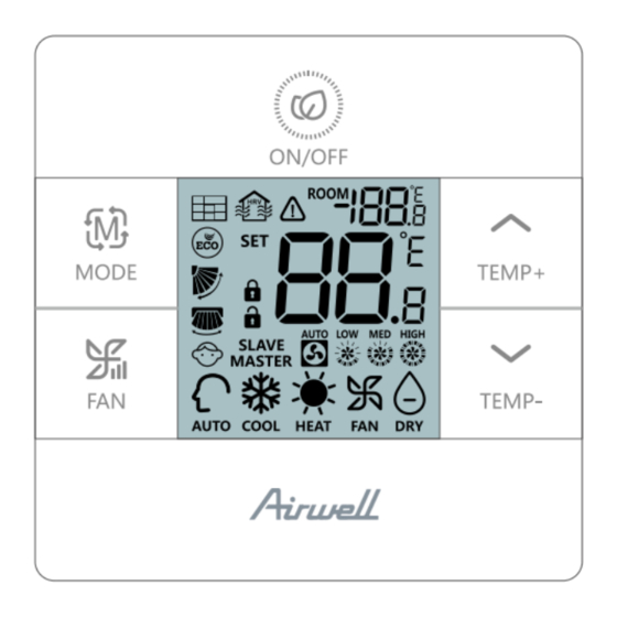
- Page 3 Parts and Functions Interface Display Full display...
- Page 4 Parts and Functions ON display...
- Page 5 Parts and Functions OFF display...
- Page 6 Parts and Functions Icon Room temp. display; ECO parameter display; Historic error code display; Parameter display; Central address display; Temp. compensation setting display; Mode combination setting display. Set temp. display; Forced cooling LL/ forced heating HH icon display; Current error code/ unit No.
- Page 7 Parts and Functions Master/slave wired controller Auto/low/middle/high fan speed Auto mode Cooling mode Heating mode Fan mode Dry mode...
- Page 8 Operation Special function operation index Function Operational approach Under ON state, after turning on the back Function selection light, press for 5s. Under cooling mode OFF state, press Forced cooling for 5s, buzzer buzzing 2 times, and screen displaying LL Under heating mode OFF state, press Forced heating...
- Page 9 Operation Function Operational approach Under state of ON + heating mode + 30°C(if ECO mode is set, change temp. to max limit) Forced defrosting. + high fan speed, press 6 times within 5s, buzzer buzzing 3 times. Eco cooling mode parameter adjusting: under ON state, cooling mode, 30°C set temp., press together for 5s to enter...
- Page 10 Operation Function Operational approach After turning on back light, press for 5s to enter error inquiry state; under error inquiry Error inquiry state, press for 5s to clear current and historic error code. Under OFF state, press for 10s to enter Wired controller setting, then press...
- Page 11 Operation Dip switch definition 8 bits dip switch (SW1) Default Sw1 Slave wired controller Master wired controller Without displaying Sw2 Displaying room temp. room temp. Collect ambient temp. Collect ambient Temp. from PCB of indoor from wired controller Non-volatile memory Non-volatile memory invalid valid Old protocol (models...
- Page 12 Operation 4 bits dip switch (SW2) Default Mode set limit Normal Buzzer no buzzing when pressing key (buzzer normally when using Normal remote control) Reserved Reserved Reserved Reserved Initialization Power on and starts initialization2 seconds later, 88.8 on top right corner and 88.8 in the middle will alternately flash until initialization finished.
- Page 13 Operation Backlight and screensaver (1) Power on, backlight comes on, green light comes on; Power off, backlightgoes out, green light goes out. (2) If SW1-6 is on, there is no screensaver, backlight is always on after power on, backlight goes out if no operations within 15s.
- Page 14 Operation • Under the condition that unit is switched off in heating mode, long press for 5s, buzzer rings twice quickly, indoor unit enter forced heatin mode, “HH” flashes in ambient display area(on top right corner), press ON/OFF button or receiving remote signal to quit forced heating mode. Mode key • ...
- Page 15 Operation Temp+/- key • Press temperature+/- to change speed by 0.5°C; • Temperature range under Auto, Cooling, Dehumidify, Heating: 16°C~30°C (If ECO is set, temperature range will change according to the setting parameters). • Temperature is set independently under Auto, Cooling, Dehumidify and Heating mode, setting temperature under each mode will be saved even mode is changed or power off.
- Page 16 Operation Filter clean reminding and filter reset cumulative time of filter is up, display on wired controller screen, when unit is running, make backlight on and long press for 5s to enter cycle function, when flashes, press to select filter reset. Adjust ECO parameters • Adjust cooling ECO parameters: Switch on indoor unit, set cooling mode, 30°C, long press for 5s, parameters will be displayed by 2 eight-segment LED in ambient display...
- Page 17 Operation Child lock: Press at the same time and hold for 5s to set Child lock function, when child lock function is successfully set will display and buzzer rings one time. If child lock function is valid now, press at the same time and hold for 5s to cancel Child lock function, child lock icon disappears and buzzer rings one time.
- Page 18 Operation • Under lowest Fahrenheit temperature(lowest temperature is 60°F when ECO is not set, if ECO is set, lowest temperature is the lower limit of ECO mode), long press for 15s to switch to Celsius; highest temperature is 30°C (it’s 30°C if ECO is se;...
- Page 19 Operation How to check error: • If there is error will display. • Check error: Make backlight on, long press for 5s, history error will be displayed by 2 eight-segment LED which is on top right corner, current error will be displayed by 2 eight-segment LED which is in the middle area, if no error, display“--”, the eight-segment LED after decimal shows unit sequence number, 0~F corresponds to 00~15 indoor unit.
- Page 20 Operation Mode restriction function: • If SW1-2 is on, mode restriction function valid. Mode key is invalid, press mode key, buzzer rings but mode cannot be changed, current mode will flash 3S to tell that current mode cannot be changed. • Under mode restriction mode, mode cannot be changed by mode key on wired controller, but mode can be changed by other source, like remote controller send signal to wired controller, central controller, change indoor mode directly by...
- Page 21 Operation • Quit inquiry mode if no operation within continuous 10s; press mode key under parameter inquiry mode to quit directly instead of changing mode; press ON/OFF under parameter inquiry mode, unit will be switched on/off. Indoor address inquiry and setting (Applies to some model): • ...
- Page 22 Operation Mode combination setting: • Keep indoor unit off, make backlight on, long press for 10 to enter mode combination setting. In temperature display area relevant value will display, default is 0, press to change. • 0-Auto-Heat-Dehumidify-Cool-Fan 1-Cool -Heat-Dehumidify 2-Cool 3-Heat 4-Heat -Dehumidify -Cool –Fan 5-Dehumidify -Cool -Fan...
- Page 23 Wired Controller Wiring Instruction Wiring Connections of Wire Controller Indoor 1 Indoor 2 Indoor N Indoor 15 Indoor 16 (master unit) Wire controller Wire controller Wire controller Wire controller Wire controller Control wiring of wire controller, polar. Wire controller Indoor 1 Indoor 1 Wire controller Wire controller...
- Page 24 Wired Controller Wiring Instruction Communication wiring Communication wiring length (m/ Dimensions of wiring 0.3mm x3-core shielded < 100m/328ft wire (22AWG,3wire) 0.5mm x3-core shielded ≥100m/328ft and <200m/656ft wire (20AWG,3wire) 0.75mm x3-core shielded ≥200m/656ft and <300m/984ft wire (18AWG,3wire) 1.25mm x3-core shielded ≥300m/984ft and <400m/1312ft wire (16AWG,3wire) x3-core shielded wire ≥400m/1312ft and <500m/1640ft (14AWG,3wire) *One side of the shielded sheet of communication wire must...
- Page 25 Wired Controller Wiring Instruction Installation diagrams 1.To take the front panel and back panel apart by screw driver. 2.To fix the back panel. 3.Insert connector of wire harness into terminal block. 4.Finally, recombine the front panel and back panel, just like below shows...
- Page 26 AIRWELL RESIDENTIAL SAS 10, Rue du Fort de Saint Cyr, 78180 Montigny le Bretonneux - France www.airwell-res.com...
Need help?
Do you have a question about the RWV03 and is the answer not in the manual?
Questions and answers