Advertisement
Quick Links
Advertisement

Related Manuals for iroda SolderPRO 150K


Summary of Contents for iroda SolderPRO 150K
- Page 2 IMPORTANT SAFETY • Be extremely careful as torch flame tip temperature is over 1300°C INSTRUCTIONS (2400°F) • Be extremely careful as torch flame is almost invisible in daylight or Warnings: under strong light. • Unit uses flammable gas (Butane) under pressure – use with care. • Use Safety Glasses. • DO NOT expose to heat above +50°C (120°F) and avoid prolonged • Do not touch the heated tip of the unit. exposure to the sun. • DO NOT leave unit unattended when operating or hot. • DO NOT puncture or incinerate. • Always be sure unit is cool before storing. • DO NOT refill, ignite or use near open flame, heater, furnace or • DO NOT replace cap without switching unit off and ensuring tip has combustible materials. cooled. • Keep work area clean. Cluttered areas and benches invite injuries. • If your torch malfunctions do not try to repair. Contact your dealer • KEEP AWAY FROM CHILDREN. Visitors should be kept away from or online support for help. work area. • Butane-Propane mix or other fuel could create much higher • Store in dry, locked cabinet out of reach of children.
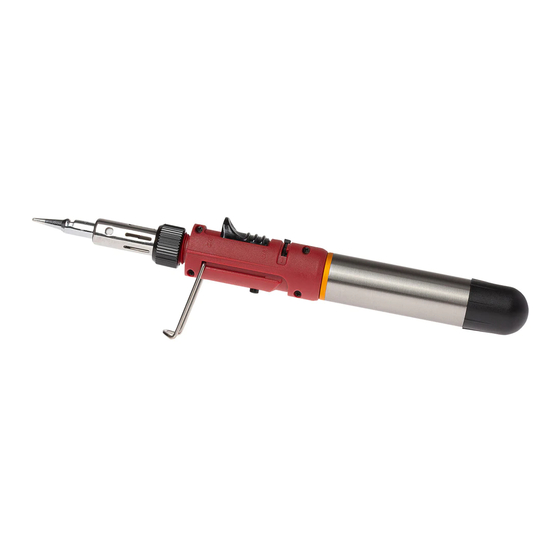
- Page 3 DESCRIPTION ON/OFF Gas Knurled Soldering Ignition Control Switch Lever LEC Chamber Tip Assembly Safety Button Safety Stand...
- Page 4 HOW TO USE THE SOLDERPRO 150K Insert LEC into Torch Fig.2 1. Remove Chamber Cap at bottom of torch. REFILLING LEC 2. Insert LEC into chamber with gray flat side toward (Liquid Energy Cell) inside of chamber. 3. Do not force LEC into chamber. Chamber Cap will • Use only high-quality butane gas. Fig.2 properly seat the LEC in chamber when screwed on. • Refill in a well-ventilated area away from any ignition 4. Replace Chamber Cap. source and other people. 1. Hold butane canister upside down when filling (Fig. 1) Fig.1 2. Firmly press canister nozzle into Gas Filling Valve. 3. O bserve fuel level and stop filling when 90% Full.
- Page 5 IGNITION 1. Set Gas Control Lever at mid position. (Fig. 3) 2. While pushing in and holding the SAFETY BUTTON (Fig. 4) Slowly slide up the ON/OFF Ignition Switch (Fig. 5) to the "ON" position to start the flow of gas. 3. As gas is flowing, continue sliding the Ignition Switch toward the tip till you hear a click. The automatic ignition will light the gas. 4. Release the switch and it will automatically move back to the "ON" position. 5. The tip housing will start to glow red. If not, slide the ON/OFF Ignition Switch back to the “OFF” position and repeat steps 2 and 3. 6. To turn off, slide the ON/OFF Ignition Switch downward to the Fig.3 Fig.4 Fig.5 OFF position.
-
Page 6: Temperature Adjustment
IGNITION WARNINGS TEMPERATURE ADJUSTMENT • Do not touch Tip, Tip Housing or Knurled Nut while igniting. (Fig. 6) • The tip temperature can be adjusted by turning • Do not ignite torch when Tip Assembly is not screwed on. (Fig. 7) the Gas Control Lever left or right. (Fig. 8) • Set to mid-position when soldering or brazing. • Excessive gas flow, flare-up or catalyst pulsing red may occur when the Gas Control Lever is set too high. Mid-Position Fig.8 Fig.6 Fig.7... - Page 7 CHANGING TIPS Knurled CHANGING TIPS CLEANING OR REPLACING NOZZLE 1. Be sure the tip has cooled before ASSEMBLY removal. 2. Unscrew Tip Assembly with a counterclockwise motion. (Fig. 9) Pliers may be required to lightly grasp the Nozzle Assembly Fig.10 Knurled Nut in order to loosen the tip. 3. Replace with desired tip. Be careful not 1. Remove Tip Assembly to overtighten as this could damage the thread in the cap. 2. Unscrew Nozzle Assembly (A) from the Torch Body (C). (Fig. 10) Pliers may be used to lightly grasp the shank in order to WARNING: The catalyst inside the Fig.9 loosen it. Do not grasp and turn the Ceramic Head.
- Page 8 4. Soak Orifice Connector in Naphtha or other similar solvent for CLEANING approximately 5 minutes. • Use only mild soap and a damp cloth to clean the housings of 5. Replace new (or clean) Orifice connector (B) remembering to the tool. Many household cleaners contain chemicals which insert the shorter side into the Torch Body. could seriously damage the plastic. Also do not use gasoline, 6. Replace Nozzle Assembly and hand tighten or tighten gently with turpentine, lacquer or paint thinner, dry cleaning fluids or similar pliers grasping the shank of the Nozzle Assembly not the ceramic products. Never let any liquid get inside the tool; never immerse head. any part of the tool into a liquid. 7. Replace Tip Assembly.
-
Page 9: Troubleshooting
TROUBLE SHOOTING Tip does a. Used-up catalyst (inside a. Replace with new tip. not heat up Tip Housing) b. Adjust control lever to a • To reduce the risk of personal injury, property damage, or damage b. Insufficient fuel pressure higher position. to your SOLDERPRO 150K, do not attempt to repair the unit body. c. Clogged orifice connector c. Clean or replace with new PROBLEM PROBABLE CAUSE HOW TO CORRECT one. Does not a. Empty Gas Tank a. Refill with butane fuel ignite b. Too high or low fuel b. Adjust control lever to a pressure higher or lower position. SPECIAL WARNING c. Pushing on/off ignition... -
Page 10: Specifications
SPECIFICATIONS Length W / Cap 272 mm (10.7 inches) W / Soldering Tip 263 mm (10.4 inches) Width 28 mm (1.1 inches) Height W / Stand 65 mm (2.6 inches) W / O Stand 36 mm (1.4 inches) Weight Empty Fuel Tank 193 g ± 2 g Watt 30 W - 125 W This appliance may be filled with any cartridges marked Approximate Soldering Tip ≈ 842 ℉ (450 ℃) “Butane” complying with EN 417. Temperature Hot Blower ≈ 1300 ℉ (650 ℃) Warning: Deflector ≈ 1300 ℉ (650 ℃) -Use outdoors only or use in well ventilated areas. -Read the instructions before using the appliance. Capacity Gas Container 15 ml (0.5 oz) CAUTION: Flame Length Mid Setting 1.2 cm (0.5 inches) -Accessible parts may be very hot. Keep young children Operating Time Mid Setting / One Gas Filling 115 min. away from the appliance. - Page 11 www.pro-iroda.com...
Need help?
Do you have a question about the SolderPRO 150K and is the answer not in the manual?
Questions and answers