Table of Contents
Advertisement
T
ECHNICAL INFORMATION
Model No.
Description
C
ONCEPT AND MAIN APPLICATIONS
Model DPT351 is a Cordless pin nailer powered by 18V Li-ion battery of
BL1815 (1.3Ah), BL1815N (1.5Ah), BL1820 (2.0Ah), BL1830 (3.0Ah),
BL1840 (4.0Ah) or BL1850 (5.0Ah).
Its main features are the same as model BPT351 as follows:
・"Hose less" enables to perform efficient operation in interior finish work
without being disturbed by air hose.
・Uses pin nails from 18 to 35mm (11/16" to 1-3/8")
・Ergonomic handle with soft grip provides comfortable grip, more control
and minimum hand fatigue and pain.
・Double trigger prevents accidental shooting.
・Depth adjustment
・Anti-dry-fire mechanism protects workpiece from damages; activates to
lock the trigger when there are 3 to 0 nails remaining in the magazines.
・Single LED job light for illuminated operation; turns on when the safety
trigger is pulled.
・Belt clip
S
pecification
Specification
Voltage: V
Capacity: Ah
Battery
Energy capacity: Wh
Cell
Charging time: min
Length: mm (")
Pin nails
(23Ga)
Diameter: mm (")
Magazine capacity: pcs.
Weight according to
EPTA-Procedure 01/2003: kg (lbs)
*1 With BL1815/BL1815N/BL1820
*2 With BL1830/BL1840/BL1850
S
tandard equipment
Safety goggles
Nose adapter
Hex wrench 3
Belt clip
*3 Battery, charger and plastic carrying case are not supplied with "Z" model.
*4 Supplied with the same quantity of extra Battery
Note: The standard equipment may vary by country or model variation.
O
ptional accessories
Pin nails; 18mm (11/16"), 25mm (1"), 30mm (1-3/16"), 35mm (1-3/8")
Belt clip
Li-ion Battery BL1850
Li-ion Battery BL1840
Li-ion Battery BL1830
Li-ion Battery BL1820
Li-ion Battery BL1815N
Li-ion Battery BL1815
Battery protector
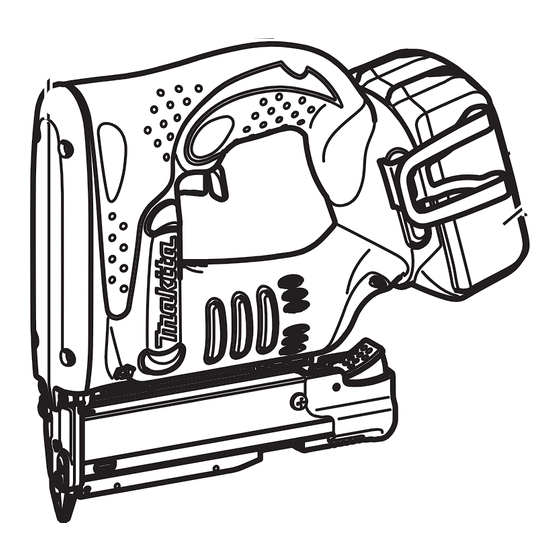
DPT351
Cordless Pin Nailer
Model No.
1.3, 1.5, 2.0, 3.0, 4.0, 5.0
24, 27, 36, 54, 72, 90
15, 15, 24, 22, 36, 45 with DC18RC
(11/16, 1, 1-3/16, 1-3/8)
Battery
*3
Charger
*3
Battery cover
*4
Plastic carrying case/Connector plastic case (Type2)
DPT351
18
Li-ion
18, 25, 30, 35
0.6 (1/32)
130
1.9 (4.2)
*1
2.1 (4.6)
*2
*3
Fast charger DC18RC
Charger DC18SD
Charger DC24SC
Automotive charger DC18SE
Four port multi charger DC18SF
Two port multi fast charger DC18RD
OFFICIAL USE
for ASC & Sales Shop
PRODUCT
P 1/ 15
L
H
Dimensions: mm (")
Length (L)
249 (9-3/4)
Width (W)
79 (3-1/8)
Height (H)
227 (8-15/16)
W
Advertisement
Table of Contents


Need help?
Do you have a question about the BL1815N and is the answer not in the manual?
Questions and answers