Advertisement
Table of Contents
- 1 Table of Contents
- 2 Important Safety Instructions
- 3 Technical Data
- 4 Warning
- 5 Component Identification
- 6 Installation
- 7 Pressure Relief Procedure
- 8 Operation Instruction
- 9 Airless Sprayer Cleaning Procedure
- 10 Pressure Release Procedure
- 11 Daily Maintain
- 12 General Repair Information
- 13 Troubleshooting
- 14 Parts List
- 15 Sealing Ring Replace
- 16 Airless Sprayer Electrical Installation Drawing
- Download this manual
Operating Instruction and Safety Manual
Electric Airless Sprayer
Model No.:
R450 220V
—
For portable spray application of architectural paints and coatings
:
1. Must be grounded: Read Grounding instructions. Use only grounded
electrical outlets or Ground equipment and conductive objects in work area.
2. Have heart problem or with heart pacemaker people, strictly prohibit to use
this machine.
R455 120V
Important Safety Instructions:
Contents
Read all warnings and instructions in
this manual. Save these instructions.
1
2014
Advertisement
Table of Contents

Related Manuals for Rongpeng R450


Summary of Contents for Rongpeng R450
- Page 1 Operating Instruction and Safety Manual Electric Airless Sprayer Model No.: R450 220V R455 120V — For portable spray application of architectural paints and coatings Important Safety Instructions: Contents Read all warnings and instructions in this manual. Save these instructions. 1. Must be grounded: Read Grounding instructions. Use only grounded electrical outlets or Ground equipment and conductive objects in work area.
-
Page 2: Table Of Contents
◎ Important safety instructions……………………………………………………2~3 ◎ Technical Data……………………………………………………………………...3 ◎ Warning ……………………………………………………………………………..4~7 ◎ Component Identification…………………………………………………………7 ◎ Installation……………………………………………………………………………7~10 ◎ Pressure Relief Procedure………………………………………………………...10~11 ◎ Operation instruction………………………………………………………………11~13 ◎ Airless Sprayer Cleaning Procedure……………………………………………..13 ◎ Pressure release procedure………………………………………………………13 ◎ Daily Maintain…………………………………………………………………………13 ◎ General Repair Information…………………………………………………………14 ◎ Troubleshooting……………………………………………………………………..15 ◎... -
Page 3: Technical Data
12) Do not spray any material there the hazard is not know. Technical Data TYPE: R450 R455 Power requirements 230±10%Vac, 50±1Hz 110±10%Vac, 60±1Hz Input power 1.2HP(900W) -
Page 4: Warning
Warning The following warnings are for the setup, use, grounding, maintenance and repair of this equipment. The exclamation point symbol alerts you to a general warning and the hazard symbol refers to procedure-specific risks. Refer back to these warnings. Additional, product-specific warnings may be found throughout the body of this manual where applicable. FIRE AND EXPLOSION HAZARD Flammable fumes, such as solvent and paint fumes, in work area can ignite or explode. - Page 5 WARING EQUIPMENT MISUSE HAZARD Misuse can cause death or serious injury. • Do not exceed the maximum working pressure or temperature rating of the lowest rated system component. Read Technical Data in all equipment manuals. • Use fluids and solvents that are compatible with equipment wetted parts. Read Technical Data in all equipment manuals. Read fluid and solvent manufacturer’s warnings.
- Page 6 TOXIC FLUID OR FUMES HAZARD Toxic fluids or fumes can cause serious injury or death if splashed in the eyes or on skin, inhaled, or swallowed. • Read warnings to know the specific hazards of the fluids you are using. •...
-
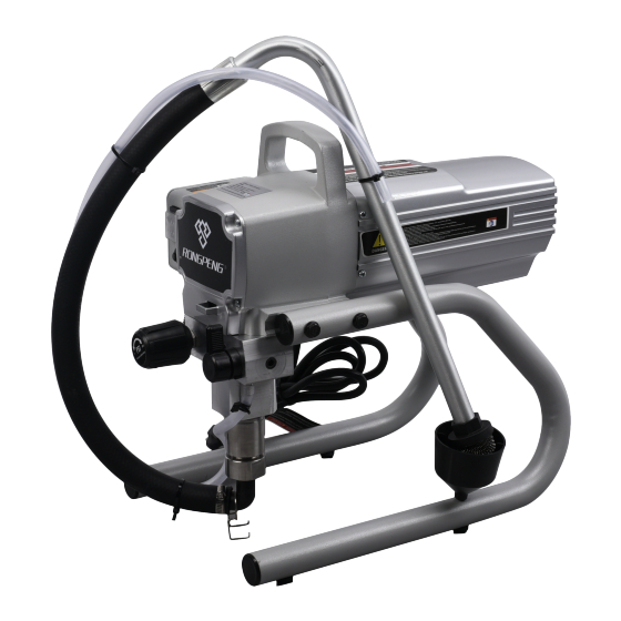
Page 7: Component Identification
Component Identification Number Description Function Introduction Pressure Adjust Knob Control output pressure of Paint(Clockwise increase pressure, anticlockwise decrease pressure) Electrical Switch Control the sprayer on or off Pressure Relief Valve Horizontal direction means paint operating condition, Vertical direction means paint pressure relief condition Fluid Outlet Paint Output Tube Suction Tube... - Page 8 If repair or replacement of the cord or plug is necessary, do not connect the green grounding wire to either flat blade terminal. The wire with insulation having a green outer surface with or without yellow stripes is the grounding wire and must be connected to the grounding pin.
- Page 9 To maintain grounding continuity when flushing or relieving pressure: hold metal part of the spray gun firmly to the side of a grounded metal pail, then trigger the gun. Locking and Unlocking the Spray Gun: Always lock the trigger off when attaching the spray tip or when thr spray gun is not in use.
-
Page 10: Pressure Relief Procedure
the pump assembly. The spray gun assembly shall also provide an external means to dissipate static electricity during the cleaning process when spraying into a metal container. Construction Black hose is constructed of an extruded, seamless themoplastic inner tube, chemically bonded to multi-layers of high tensile synthetic resistant polyurethane cover. -
Page 11: Operation Instruction
4. If you suspect the spray tip or hose is clogged or that pressure has not been fully relieved after following the steps above, VERY SLOWLY loosen tip guard retaining nut or hose end coupling to relieve pressure gradually, then loosen completely. Clear hose or tip obstruction. - Page 12 3. Install guard over end of gun 4. Insert tip in guard.Tighten retaining nut. Operation Spraying 1. Unlock trigger lock 2. Be sure the tip faces forward spray. 3. Hold gun perpendicular and approximately 12 inches (304mm) from surface.Move gun first, Then pull gun trigger to spray a test pattern.
-
Page 13: Airless Sprayer Cleaning Procedure
Airless Sprayer Cleaning Procedure When spraying tip is block-up, revolve it 180 degree for several times, then move back in position of well-spraying. Fig.5 Step 1: Engage trigger safety lock on gun. Revolve 180 degree Step 2: Turn off pump and release fluid pressure by turning the pressure relief prime valve located on the engage trigger safety lock on gun. -
Page 14: General Repair Information
General Repair Information Flammable materials spilled on hot, bare, motor could cause fire or explosion. To reduce risk of burns,fire or explosion, do not operate sprayer with coverremoved. • Keep all screws, nuts, washers, gaskets, and electrical fittings removed during repair procedures. These parts usually are not provided with replacement kits. -
Page 15: Troubleshooting
Troubleshooting 1. Common Problem of Equipment Problem What To Check What To Do (If check is OK, go to next check) (When check is not OK, refer to this column) Motor Won’t Operate 1. Pressure control knob setting. Motor will 1.Slowly increase pressure setting to see if not run if set at minimum (fully motor starts... - Page 16 Explode view...
-
Page 17: Parts List
Parts list Description Qty. Description Qty. Description Qty. Motor cover Decompression valve spring Valve plates under copper gaskets Cross recess head screw Spring seat Feed base (M4X10) Motor assembly Elastic cylindrical pin 3X8 Hexagon socket cap screws Wave spring washers Switch base Discharge joint Hexagon socket cap screws... -
Page 18: Sealing Ring Replace
Sealing ring replace: Before the repair, please be sure to determine the equipment fault, otherwise the unnecessary dismantling of equipment will seriously affect the function of the equipment and greatly shorten the service life of equipment. With cross screwdriver down pump casing。 With cross screwdriver down the cover of a gear box. -
Page 19: Airless Sprayer Electrical Installation Drawing
R450 Airless Sprayer Electrical Installation Drawing Electricity (230V) Heat Pressure Control Protection Switch Electrical Micro Computer Controlled Switch Board Motor R455 Airless Sprayer Electrical Installation Drawing Electricity (110V) Heat Pressure Control Protection Switch Electrical Switch Micro Computer Controlled Board Motor...
Need help?
Do you have a question about the R450 and is the answer not in the manual?
Questions and answers