Table of Contents
Advertisement
Operating Instruction and Safety Manual
Electric Airless Sprayer
Model No.:
R470 220V
—
For portable spray application of architectural paints and coatings
:
1. Must be grounded: Read Grounding instructions. Use only grounded
electrical outlets or Ground equipment and conductive objects in work area.
2. Have heart problem or with heart pacemaker people, strictly prohibit to use
this machine.
R475 120V
Important Safety Instructions:
Contents
Read all warnings and instructions in
this manual. Save these instructions.
1
2014
Advertisement
Table of Contents

Related Manuals for Rongpeng R475 120V


Summary of Contents for Rongpeng R475 120V
- Page 1 Operating Instruction and Safety Manual Electric Airless Sprayer Model No.: R470 220V R475 120V — For portable spray application of architectural paints and coatings Important Safety Instructions: Contents Read all warnings and instructions in this manual. Save these instructions. 1. Must be grounded: Read Grounding instructions. Use only grounded electrical outlets or Ground equipment and conductive objects in work area.
-
Page 2: Table Of Contents
◎ Important safety instructions……………………………………………………2~3 ◎ Technical Data……………………………………………………………………...3 ◎ Warning ……………………………………………………………………………..4~7 ◎ Component Identification…………………………………………………………7 ◎ Installation……………………………………………………………………………7~10 ◎ Pressure Relief Procedure………………………………………………………...10~11 ◎ Operation instruction………………………………………………………………11~13 ◎ Airless Sprayer Cleaning Procedure……………………………………………..13 ◎ Pressure release procedure………………………………………………………13 ◎ Daily Maintain…………………………………………………………………………13 ◎ General Repair Information…………………………………………………………14 ◎ Troubleshooting……………………………………………………………………..15 ◎... -
Page 3: Technical Data
2) Keep hands and other body parts away from the discharge. For example, do not try to stop leaks with any part of the body. 3) Always use the nozzle tip guard. Do not spray without nozzle tip guard in place. 4) Only use a nozzle tip specified by the manufacturer. -
Page 4: Warning
Warning The following warnings are for the setup, use, grounding, maintenance and repair of this equipment. The exclamation point symbol alerts you to a general warning and the hazard symbol refers to procedure-specific risks. Refer back to these warnings. Additional, product-specific warnings may be found throughout the body of this manual where applicable. FIRE AND EXPLOSION HAZARD Flammable fumes, such as solvent and paint fumes, in work area can ignite or explode. -
Page 5: Warning
WARING EQUIPMENT MISUSE HAZARD Misuse can cause death or serious injury. • Do not exceed the maximum working pressure or temperature rating of the lowest rated system component. Read Technical Data in all equipment manuals. • Use fluids and solvents that are compatible with equipment wetted parts. Read Technical Data in all equipment manuals. Read fluid and solvent manufacturer’s warnings. - Page 6 TOXIC FLUID OR FUMES HAZARD Toxic fluids or fumes can cause serious injury or death if splashed in the eyes or on skin, inhaled, or swallowed. • Read warnings to know the specific hazards of the fluids you are using. •...
-
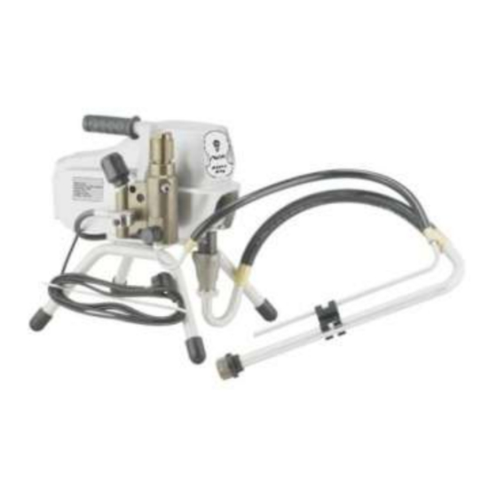
Page 7: Component Identification
Component Identification Number Description Function Introduction Pressure Adjust Knob Control output pressure of Paint(Clockwise increase pressure, anticlockwise decrease pressure) Electrical Switch Control the sprayer on or off Pressure Relief Valve Horizontal direction means paint operating condition, Vertical direction means paint pressure relief condition Fluid Outlet Paint Output Tube Suction Tube... - Page 8 grounded in accordance with all local codes and orinances. Improper installation of the grounding plug can result in a risk of electric shock. If repair or replacement of the cord or plug is necessary, do not connect the green grounding wire to either flat blade terminal.
- Page 9 a water pipe. To maintain grounding continuity when flushing or relieving pressure: hold metal part of the spray gun firmly to the side of a grounded metal pail, then trigger the gun. Locking and Unlocking the Spray Gun: Always lock the trigger off when attaching the spray tip or when thr spray gun is not in use.
-
Page 10: Pressure Relief Procedure
A hose, hose assembly, and spray gun assembly shall be constructed to provide electrical bonding to dissipate static electricity from the tip of the Spray gun through the spray gun assembly and the couplings at the ends of the hose to the pump assembly. -
Page 11: Operation Instruction
4. If you suspect the spray tip or hose is clogged or that pressure has not been fully relieved after following the steps above, VERY SLOWLY loosen tip guard retaining nut or hose end coupling to relieve pressure gradually, then loosen completely. Clear hose or tip obstruction. - Page 12 1. If equipment has recently been operated, Relieve pressure.Set trigger lock 2. Using a pencil or similar object, Insert seal into back of guard. 3. Install guard over end of gun 4. Insert tip in guard.Tighten retaining nut. Operation Spraying 1.
-
Page 13: Airless Sprayer Cleaning Procedure
Airless Sprayer Cleaning Procedure When spraying tip is block-up, revolve it 180 degree for several times, then move back in position of well-spraying. Fig.5 Step 1: Engage trigger safety lock on gun. Revolve 180 degree Step 2: Turn off pump and release fluid pressure by turning the pressure relief prime valve located on the engage trigger safety lock on gun. -
Page 14: General Repair Information
General Repair Information Flammable materials spilled on hot, bare, motor could cause fire or explosion. To reduce risk of burns,fire or explosion, do not operate sprayer with coverremoved. • Keep all screws, nuts, washers, gaskets, and electrical fittings removed during repair procedures. These parts usually are not provided with replacement kits. -
Page 15: Troubleshooting
• Do not run sprayer dry for more than 30 seconds. Doing so could damage pump packings. • Protect the internal drive parts of this sprayer from water. Openings in the cover allow for air cooling of the mechanical parts and electronics inside. If water gets in these openings, the sprayer could malfunction or be permanently damaged. - Page 16 9. Motor brushes binding in brush holders. 9. Clean brush holders. Remove carbon dust by using compressed air to blow out brush dust. 10. Low stall pressure. Turn pressure 10. Replace pressure control assembly. control knob fully clockwise. 11. Motor armature for shorts by using an 11.
-
Page 17: Parts List
Parts list Description Qty. Description Qty. Description Qty. Filter assembly Powder metallurgy gear shaft collar O-Rings(27x2.4) Ribbon Gear shaft Feed pipe bending Pinion Allen flat end set screws M3X10 cutting ferrule Bent axle Deflating cap Feeding hose Crankshaft gear Micro switch cover Pressure release tube Retaining ring... -
Page 18: Sealing Ring Replace
Plunger lever The power cord fixing seat Rack pads The piston locking collar Power Plugs Pump seat assembly Piston The handle cushion Pressure gauge(Rc1/4 contact) Connecting rod handle Internal tooth lock washer Axis Guide The handle sheath plain washer Straight pin Heat sink spring washer Straight pin... -
Page 19: Airless Sprayer Electrical Installation Drawing
1. Remove Pump’s front cover. Use a special tool to take out the plunger rod connecting pin 3. Lose the cap 4. Unscrew the pump body components,separately on the pump body and feedstock block. 5. Take out the plunger rod in the opposite direction,take out the ring size 6. - Page 20 1. Left Secondary Frame (With Handle Grip) 1PCS 2. Right Secondary Frame (With Handle Grip) 1PCS 3. White Seal Washer 3PCS 4. Black Seal Washer 2PCS...
Need help?
Do you have a question about the R475 120V and is the answer not in the manual?
Questions and answers