
Related Manuals for LINDR CWP 300


Summary of Contents for LINDR CWP 300
- Page 1 INSTRUCTION MANUAL UNDERCOUNTER COOLERS LINDR ENGLISH Number 020-2020 REV00 Valid 2020-10-01 MODEL CWP 300 4 PUMPS GREEN LINE MODEL CWP 300 4 PUMPS WITH DIGITAL THERMOSTATS GREEN LINE...
- Page 2 Sadová 132 503 15 Nechanice, Czech Republic mob.: + 420 775 715 494 tel. : +420 495 447 239 e-mail: info@lindr.cz web: www.lindr.cz, www.lindr.eu SYMBOLS AND MARKINGS USED IN THE MANUAL: WARNING: NOTE: Not following instructions may cause injury or This symbol indicates information and damage the device.
-
Page 3: Table Of Contents
Contents: Introduction ........Description of the cooler ........Machine plate .. -
Page 4: Introduction
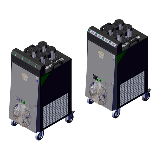
1. INTRODUCTION: The supplier is not liable for damage caused by activities carried out on this device without Thank you for purchasing this LINDR product. observing the following instructions! 2. DESCRIPTION OF THE COOLER: CWP 300 4 PUMPS GREEN LINE:... -
Page 5: Installation And Placement
• Ensure sufficient free space for air circulation WARNING: When unplugging the device and heat dissipation. from the socket, grab the plug and pull it out. • Ensure sufficient supply of fresh air. Do not under any circumstances pull at the •... -
Page 6: Electrical Connection
6. ELECTRICAL CONNECTION: product in a way that is counter to the instructi- on manual or the product‘s design as defined Connect the device to a power socket in ac- by the manufacturer. Materials replaced du- cordance with specifications on the machine ring the validity period of the warranty are our plate of the device. - Page 7 Model: CWP 300 4 PUMPS Green Line Model: CWP 300 4 PUMPS Green Line 1x thermostat with digital thermostat figure...
-
Page 8: Putting Into Operation
10. PUTTING INTO OPERATION: 1. Connect the cooling device to double-walled tanks, cooling coils or plate heat exchangers (see picture no. 11 A Connection diagram of the cooler with tanks). NOTE: For connection use only the fittings and clamps specified by the supplier. Use ca- librated hoses. -
Page 9: Stc 200 Thermostat
-walled tanks, external vessels. 13. MECHANICAL THERMOSTAT: Cooler temperature CWP 300 4 PUMPS Green Line with digital thermostats is controlled by a mechanical thermostat, which is located on the radiator door and monitors the water bath tem- perature in the range of 0 - 12 ° C. - Page 10 14. PLASTIC TANK FILLING AND CONNECTION WITH BEER TANKS: • Fill the plastic tank with liquid without chemical additives up to the MAX mark. • Connect the device to the tank using the speed fittings. 10 A 10 B figure figure Pour liquid here WARNING: When the pumps are switched on, the water from the plastic tank will be...
-
Page 11: Connection Diagram Of The Cooler With Tanks
15. CONNECTION DIAGRAM OF THE COOLER WITH TANK: 11 a figure Double-walled tank Hose 12,7mm + insulation, input from the tank to the double-walled tank Temperature probe 6m Hose 12,7mm + insulation, output from the tank to the cooling device Cooling device CWP 300 4x pump... -
Page 12: Cleaning The Condenser
16. CLEANING THE CONDENSER: The condenser must be cleaned with compressed air 1x a month. Alternatively, clean with a brush. 12 A figure 12 B 12 C figure figure WARNING: The condenser must only be cleaned by professional personnel and at least 1x a month by brushing or by compressed air. -
Page 13: Inspection Before Every Use
17. INSPECTION BEFORE EVERY USE: 1. Visual check. 2. Lead-in cable check. 3. Condenser cleanliness check (in case of excess pollution of the condenser, clean more frequently than 1x a month). 4. Inspection of water level. WARNING: Do not use the device if defects or malfunctions are found. 18. -
Page 14: Table Of Malfunctions
21. TABLE OF MALFUNCTIONS: Malfunction Cause Removal The device is too noisy. The device is in contact Move the object that is touching the with a foreign object. device so that it is not in contact with the cooler. There is a sunken foreign object in the fan com- Remove the object from the fan com- partment. -
Page 15: Spare Parts
When ordering spare parts, always provide the following: • product type • production year • product‘s serial number 23. TECHNICAL DATA: CWP 300 4 PUMPS CWP 300 4 PUMPS Green Line Name Green Line with digital thermostat Power (Hp) Power...
Need help?
Do you have a question about the CWP 300 and is the answer not in the manual?
Questions and answers