
Subscribe to Our Youtube Channel
Related Manuals for LINDR Pygmy 25-K Exclucive-us Green Line


Summary of Contents for LINDR Pygmy 25-K Exclucive-us Green Line
- Page 1 INSTRUCTION MANUAL FOR ENGLISH LINDR CONTACT DRY COOLER Number 005-2020 REV01 Valid 2020-01-29 Pygmy 25-K Exclucive-us Green Line 1xkohout Pygmy 25-K Exclusive-us Green Line 2x kohout...
- Page 2 This manual contains instructions for installing, using and operating the machine. This manual is an integral part of the machine. It must be stored at the equipment for the life of the equipment and provided to the user whenever it is installed, moved, used, or maintained.
-
Page 3: Table Of Contents
Contents: …............... Introduction …............... Description of the cooler …............... Product label General instructions, measures …............... and safety instructions …............... Installation and placement …............... Electrical connection …............... Testing …............... Warranty …............... Description of the cooler …............... 11 10. Package contents …............... 12 11. - Page 4 Symbols and Markings Used in the Manual WARNING: Not following instructions may cause injury or damage the device. WARNING: Risk of injury by electrical current. NOTE: This symbol indicates information and recommendations for users. WARNING: cooling system contains flammable coolant R290 (propane)!
-
Page 5: Introduction
Time needed to accumulate energy is ca. 10 min. Lindr cooling technology has 45 % higher output than is its input energy. The... -
Page 6: General Instructions, Measures And Safety Instructions
WARNING: Cleaning 4. General Instructions, maintenance of the appliance on Measures and Safety the part of the user must not be done Instructions by unsupervised children. WARNING: Before connecting to When using the device, follow basic main electrical supply, check that the safety instructions stated... -
Page 7: Installation And Placement
WARNING: When unplugging WARNING: After unpacking, the device from the socket, grab place the cooler so that heat created the plug and pull it out. Do not under by the cooling unit can be vented any circumstances pull at the cable; sufficiently. -
Page 8: Electrical Connection
WARNING: The cooler must be 8. Warranty placed indoors (in a roofed area) on a The device comes with a warranty in dry, level, stable surface. accordance with general legal regulations of the Czech Republic or in WARNING: Protect the cooler accordance with the trade agreement. -
Page 9: Description Of The Cooler
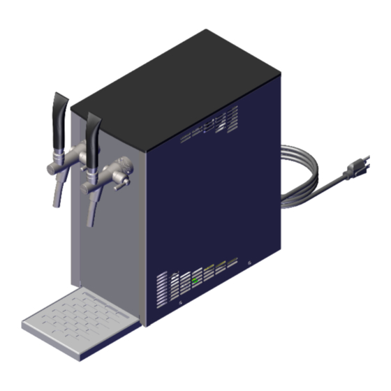
9. Description of the Cooler Pygmy 25-K-Exclusive US Green Line 1x tap Power cable Drip tray Thermostat Condenser vent grid Beverage outlet (3/8" speed fitting) Air compressor switch Product label 5 Lighting switch Air outlet (5/16" speed fitting) ˇ... - Page 10 Pygmy 25-K-Exclusive US Green Line 2x tap Power cable Drip tray Thermostat Condenser vent grid Beverage outlet (3/8" speed fitting) Air compressor switch Product label 5 Lighting switch Air outlet (5/16" speed fitting)
-
Page 11: Package Contents
10. Package Contents The package contains: 1. Tap 2. Tap wrench 3. Drip tray and sieve ˇ... -
Page 12: Tap Installation
11. Tap Installation Fit the tap perpendicularly onto the spline coupler. Secure with a flare nut and turn to the left. (loosen to the right). Tighten with the enclosed wrench. -
Page 13: Keg Coupler Assembly
12. Keg Coupler Assembly 12.1 Outlet for keg pressurisation: Connection variant with bushing: hose is fitted onto the bushing and affixed with a clip. Connection variant with rapid coupling: Screw an F 5/8“ x 5/16“ (8 mm) rapid coupling onto the keg coupler ˇ... - Page 14 WARNING: Before you screw the rapid coupling onto the 5/8“ thread, make sure the keg coupler (air inlet for delivery medium) has a non-return valve fitted on it.
- Page 15 12.2 Outlet for beverage: Screw an F 5/8“ x 3/8“ (9.5 mm) speed fitting onto the keg coupler ˇ...
-
Page 16: Beverage Supply Connection And Pressurisation
13. Beverage Supply Connection and Pressurisation Connect the cooling device to the keg coupler by plugging a 3/8“ beverage hose into the speed fitting located on the rear of the cooler marked inlet 1, inlet 2. Connect the cooling device to the keg coupler by plugging a 5/16“... - Page 17 ˇ...
-
Page 18: Inlet And Outlet Marking
14. Inlet and Outlet Marking Tap – outlet 2 Tap – outlet 1... -
Page 19: Keg Tapping And Untapping
15. Keg Tapping and Untapping WARNING: Make sure the adapter is clean before tapping the keg! S system keg coupler Procedure for tapping and untapping a keg with an S system keg coupler: 1. Keg tapping: ˇ... - Page 21 2. Keg untapping: ˇ...
- Page 22 A system keg coupler:...
- Page 23 Procedure for tapping and untapping a keg with an A system keg coupler: 1. Keg tapping: ˇ...
- Page 24 2. Keg untapping:...
-
Page 25: Putting Into Operation
16. Putting into Operation 1. Connect air supply and beverage supply according to point 13. 2. Set the thermostat to 0 position. 3. Connect the cooler to the power mains. 4. Tap the keg in accordance with point 15. 5. Turn the air compressor on using the switch and pressurise it to the required pressure of 1.0-3.4 bar (in models with built-in compressor, pressure is automatically set to 2.8-3.4 bar). -
Page 26: Thermostat Placement
17. Thermostat Placement Mechanical thermostat with 1 – 7 numerical scale located on the front of the cooler. 18. Temperature and Adjustment The temperature of the cooled beverage is controlled by a mechanical thermostat in temperature range of 2 °C to 8 °C. -
Page 27: Built-In Air Compressor
19. Built-in Air Compressor The air mini-compressor is built into the cooling device itself. The compressor can be turned off separately with a switch. Air pressure is controlled automatically in 2.8 – 3.4 bar range. The air outlet from the cooler terminates in a 5/16“ (8 mm) rapid coupling marked AIR. -
Page 28: Environmental Protection
21. Environmental Protection Waste Sorting This product must not be disposed of in communal waste. Electrical waste in Czech Republic disposed within Rema System (www.remasystem.cz), tel.: +420 225 988 001(002). In countries other than the Czech Republic, waste sorting is subject to local regulations Sorted waste enables recycling and reusing used products and packaging materials. -
Page 29: Periodic Checks
24. Periodic Checks • 1x a week: check that the lead-in cable is undamaged and that the plug is firmly in the socket. • 1x a week: check that the device is not exposed to radiant heat. • 1x a week: check that air circulation is not obstructed. •... -
Page 30: Sanitation By Water
26. Sanitation by Water (Sanitation Adapter) Connect the sanitation adapter (not included) to water mains using a hose. WARNING! Maximum water temperature must not exceed 25 °C. NOTE: Sanitation adapter is not included. Can be purchased as an accessory for the cooler. - Page 31 ˇ...
-
Page 32: Table Of Defects
27. Table of Defects DEFECT CAUSE REMOVAL beverage does keg tapped incorrectly check that the keg coupler lever is not flow pushed down device with built-in compressor - turn on the switch water from sanitation turn off the device; then you have to froze wait until the beverage starts flowing again (may take a few minutes, or... -
Page 33: Spare Parts
Do not forget to specify the following: • type of defect • type of product • production year • product's serial number (found on the label) Ordering components: ALWAYS USE ORIGINAL COMPONENTS. The manufacturer or supplier bear no responsibility for non-original components or components not recommended by the manufacturer. -
Page 34: Wiring Diagram
30. Wiring Diagram... -
Page 35: Cooling Diagram
31. Cooling Diagram...
Need help?
Do you have a question about the Pygmy 25-K Exclucive-us Green Line and is the answer not in the manual?
Questions and answers