Advertisement
Quick Links
Advertisement

Related Manuals for Okayo EJ-600DR


Summary of Contents for Okayo EJ-600DR
- Page 1 Digital Dual-channel Diversity Microphone System User Manual...
-
Page 2: Table Of Contents
Preface Thank you for the purchase of Digital Dual-channel Diversity Microphone System. This manual will give comprehensive instructions and operation. Please read it over before your use to perform this unit well. Contents Illustration ....................1 Contents Setup Procedure ..................2 Digital Wireless Receiver Module ............ -
Page 3: Contents Illustration
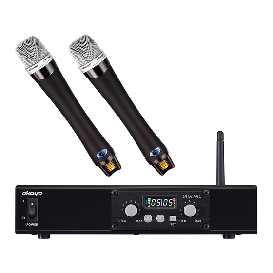
Illustration DIGITAL CH.A CH.B DC INPUT 12 15V/1A LOW/HI AF OUT 5. Unbalanced AF Output (6.3 mm jack) 1. Power Switch 6. AF Impedance Selection (for 5) Digital Wireless Receiver Module 3. Antennas 7. DC Power Socket 4. Balanced AF XLR Output Power Supply Please use our product ‘s... -
Page 4: Setup Procedure
Setup Procedure Signal Connections 1. Connect 6.3 mm mic jack from Unbalanced AF Output to amplifier s MIC IN “ ” ’ “ ” and set “impedance” at “LOW”. Or connect 6.3 mm mic jack from “unbalanced AF Output” to amplifier’s “LINE IN” and set “impedance” at “HI”. (The same way can be applied in Single-channel Diversity Receiver / Dual-channel Receiver.) Remark: AF Impedance Selection only controls Unbalanced AF Output (6.3 mm jack). -
Page 5: Digital Wireless Receiver Module
Digital Wireless Receiver Module 1. LCD display DIGITAL (channel number/ signal strength/ A channel battery meter) 2. A channel volume CH.A CH.B 3. Channel selection 4. Set key 5. B channel volume Operation Power on and Off 1. Receiver module powers on along with the PA LCD displays On and after to 2 seconds, screen displays channel number. - Page 6 Digital Wireless Receiver Module Setting channel synchronization a. When both microphones are set as Master: 1. First powered on microphone will be set as channel A, and the second is channel B. 2. When channel A microphone is shut off or out of signal for more than 5 seconds, B channel microphone auto switches to channel A.
-
Page 7: Digital Handheld Microphone
Digital Handheld Microphone 7. Talk/Mute button 1. Mesh head 8. Battery holder 2. Handheld tube 9. Battery door 3. Power indicator 10. Maser/Slave mode switch 4. Power button 11. Charging contacts 5. LCD display 6. setup wheel (Press to set, scroll up and down to adjust) Insert battery Open battery door and insert 2 AA 1.2 V (Ni-MH 1600mAh) or 2 AA 1.5 V Alkaline batteries. - Page 8 Digital Handheld Microphone Handheld method Do not block bottom signal source. Operation and Setup Power On Insert battery and press power button to turn on, power indicator (3) lights on. Blue light means battery power is efficient and red means insufficient. Volume adjustment Press setup wheel (6) then scroll up and down to adjust volume.
- Page 9 Digital Handheld Microphone Channel synchronization The microphone will automatically sync when powered on. When syncing successfully, mute key lights in blue and channel number shows. If syncing failed, then mute key lights in red and no channel number display. When microphone is set to slave mode: 1.
-
Page 10: Digital Pendant/Bodypack Transmitter
Digital Pendant/Bodypack Transmitter 1. Power/Mute switch 5. Charging indicator 9. Belt clip. 2. Volume control 6. Neck strap hole 10. Mic in 3. LCD window 7. DC input 11. AUX in 4. Mesh Head 8. Strap hole 12. Charging terminal Operation and Setup Power ON 1. - Page 11 Digital Pendant/Bodypack Transmitter Power OFF 1. Press and hold for two seconds to turn the device off. 2. OFF display on screen and all indicators turned off. Mute / Talk switch 1. Press Mute switch (1) to switch between mute and talk mode. 2.
- Page 12 Digital Pendant/Bodypack Transmitter Volume switch LCD screen will display current used volume level when press (VOL. 1 ~ 3). Reset Press then press power key to power on to enter RESET mode. The default value is Volume 2, and Master/Slave does not affect by RESET mode. Method to install neck strap The best distance is 10 CM between pendant microphone and user s chin.
-
Page 13: Important Notes / Troubleshooting
Important Notes Avoiding heat and humidity Keep the device away from any heat source and in a location with good ventilation. Do not leave it under sunlight or close to heater. DON’T operate the device in the rain or in humid circumstance to prevent failure. Prevent the device from dropping. -
Page 14: Specifications
Specifications Digital Dual-channel Receiver Receiver Module Digital wireless receiver module LCD window Channel, requency Channel adjustment Set up key, up and down key Carrier frequency 2.4 - 2.5 GHz Channels Output level Ω XLR 1 V / 600 2k Ω (Hi) Φ6.3 mm : 700 mV / 2k Ω... - Page 15 Specifications Digital Pendant/Bodypack Transmitter Microphone capsule condenser Antenna internal RF output power Max 10 dBm Audio input Mic in, Aux in Mic in jack 3.5 mm Audio control Mute, Hi/Mid/Low sensitivity Lithium (1200 mAh) Battery Running time 24 hours Dimensions (DxWxH) 32 x 52 x 88 mm 77 g (battery included) Weight...
- Page 16 12/14...