Table of Contents
Advertisement
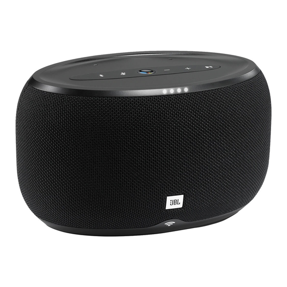
LINK 300
JBLLINK300BLKUS, JBLLINK300WHTUS, JBLLINK300BLKCA, JBLLINK300WHTCA, JBLLINK300BLKDE,
SKU:
JBLLINK300WHTDE, JBLLINK300BLKFR, JBLLINK300WHTFR, JBLLINK300BLKUK, JBLLINK300WHTUK, JBLLINK300BLKAU,
JBLLINK300WHTAU, JBLLINK300BLKJN, JBLLINK300WHTJN,
Released by Global Quality SL
Voice-Activated Speaker
CONTENTS
harman/kardon, Inc.
Service Manual
2
3
6
7
8
12
20
28
29
31
Ver. 1.2 Apr 2019
Advertisement
Table of Contents

Related Manuals for Harman JBL LINK 300


Summary of Contents for Harman JBL LINK 300
-
Page 1: Table Of Contents
CONTENTS Technical Specifications Safety Instruction, Warning & Notes Button Function Mapping Set Block Diagram Disassembly Instructions Layout Diagrams Schematic Diagrams Set Mechanical Exploded View Spare Parts List Revision List Ver. 1.2 Apr 2019 Released by Global Quality SL harman/kardon, Inc. -
Page 2: Technical Specifications
TECHNICAL SPECIFICATIONS Bluetooth version: 4.1 Transducers: 1*30W woofer; 1*5W tweeter Rated power: 30W Frequency response: 80Hz 20kHz Pink noise Test with C weighting: >85dB Power Supply:19V/2A Transmitter power: 2.402 – 2.480 GHz Bluetooth transmitter modulation :GFSK, /4 DQPSK, 8DPSK Micro USB (for software update) Class D amplifier section Dimensions (W ×... - Page 3 Contact your local waste management officials for information NOTE: Changes or modifications not expressly approved regarding the environmentally sound collection, recycling and by Harman could void the user’s authority to operate the disposal of used batteries. equipment. To remove the batteries from your equipment or remote...
- Page 4 Some semiconductor (solid state) devices can be damaged easily by static electricity. Such components commonly are called Electrostatically Sensitive (ES) Devices. Examples of typical ES devices are integrated circuits and some field effect transistors and semiconductor "chip" components. The following techniques should be used to help reduce the incidence of component damage caused by static electricity. 1.
- Page 5 SAFETY PRECAUTIONS The following check should be performed for the continued protection of the customer and service technician. LEAKAGE CURRENT CHECK Measure leakage current to a known earth ground (water pipe, conduit, etc.) by connecting a leakage current tester between the earth ground and all exposed metal parts of the appliance (input/output terminals, screwheads, metal overlays, control shaft, etc.).
-
Page 6: Safety Instruction, Warning & Notes Button Function Mapping
BOTTON FUNCTION MAPPING... -
Page 7: Set Block Diagram
4.5V for LED TPS54202 AC/DC DC DC adaptor 3.3V always on for MCU TPS54202 19V/3A DC DC Audio Signal: 5V for Audio TPS54202 3.3V for DAC /LED Power Signal: DC/DC 5V for WIFI Control Signal: TP54231 HARMAN INTERNATIONAL. CONFIDENTIAL. COPYRIGHT 2013. -
Page 8: Disassembly Instructions
Disass embly Instru uctions 1: Cut the seal ling tape 2: Open the c color box 3:Take out th he attachment 4: Take out t he product 5: Remove t the grill : Remove ru ubber foot... - Page 9 7: Remove 8 sc crews as show 8: Tak ke off the cable 9: Rem move 5 screws as shown Remove 2 screws as sho...
- Page 10 rubber 11: Remove the 12: Remove 2 screws as shown 13: Remove 4 screws as shown 15: Remove the FFC Remove the top cover cable Remove the screws...
- Page 11 Remove rubber 1 17: t t he 18: Remove t the 8 screws a a s shown 19: Rem ove the cable e...
-
Page 12: Layout Diagrams
LAYOUT DIAGRAM... -
Page 20: Schematic Diagrams
REVISION RECORD ECO NO: APPROVED: DATE: FACTORY RESET TP255 RESET_KEY TP260 VOUT CONN-4P-1.5MM TP11 ME6211A33MX R212 RESET_KEY USB_5V USB_5V USB_D- WIFI_LED_LEVEL1 MMBT3904 USB_D+ USB_ID TP257 WIFI_LED_LEVEL3 WIFI_LED_LEVEL2 WIFI_LED_LEVEL1 CON_DC_4PIN DC_JACK CON_0.5MM_32PIN WIFI_LED_LEVEL2 MMBT3904 USB_5V WIFI_LED_LEVEL3 CON1 USB_ID MMBT3904 CONN-5P-2.0 TP18 TP64 TP61 TP62 TP63 COMPANY:... - Page 21 REVISION RECORD ECO NO: APPROVED: DATE: VBUS MICRO-USB-10P_3A CON3 CONN-5P-2.0 TP61 TP62 COMPANY: TITLE: JBL_LINK30_DV2 DRAWN: DATED: ABEL <Drawn Date> CHECKED: DATED: CODE: SIZE: DRAWING NO: REV: <Checked By> <Checked Date> <Code> QUALITY CONTROL: DATED: <QC By> <QC Date> RELEASED: DATED: <Released By>...
- Page 22 REVISION RECORD ECO NO: APPROVED: DATE: 470R 470R 470R 470R 470R level3 470R R214 CONN-SMD-4P-1.5MM level2 level1 COMPANY: TITLE: JBL_LINK30_DV2 DRAWN: DATED: ABEL <Drawn Date> CHECKED: DATED: CODE: SIZE: DRAWING NO: REV: <Checked By> <Checked Date> <Code> QUALITY CONTROL: DATED: <QC By>...
- Page 23 REVISION RECORD ECO NO: APPROVED: DATE: TP26 TP52 RGB_4.5V 3.3V_MCU VOLUME UP TP25 3.3V_MCU RGB_4.5V VOL+_BUTTON R230 MIC_VCC 3.3V_MCU MIC_CLOCK VOLUME DOWN MIC_DATA TP24 VOL-_BUTTON TP35 3.3V_MCU VOICE_KEY PLAYPAUSE TP23 TP36 TP29 3.3V_MCU PLAY_BUTTON TP37 GOOGLE_ASSISTANT_BUTTON TP28 3.3V_MCU White TP38 PLAY_BUTTON BLUETOOTH TP22...
- Page 24 REVISION RECORD ECO NO: APPROVED: DATE: GND1 GND1 FB_0603 FB_0603 SELECT SELECT CLOCK CLOCK DATA DATA TP14 TP15 MIC_SILICON MIC_SILICON GND1 GND1 TP13 TP10 DATA GND1 DATA TP12 TP11 CLOCK GND1 CLOCK GND1 TP33 TP31 TP34 TP32 CLOCK DATA GND1 CONN-4P-1.25MM-BAO TP61 TP62 COMPANY:...
- Page 25 REVISION RECORD ECO NO: APPROVED: DATE: 19V 3A MOSFET ME4435 TPS54231 TPA3116 78L12 Adaptor ME6211 400K ME6211 TLV70245 3.33V 4.57V 30mA 24.4mA 4.97V 210mA 3.33V 33.8mA SGM4552 4 RGB Yoda Module LDO ME6211 PCM5121 Reverse COMPANY: TITLE: JBL_LINK30_PV DRAWN: DATED: ABEL <Drawn Date>...
- Page 26 REVISION RECORD ECO NO: APPROVED: DATE: OP_VBIAS2 OP_VBIAS1 TP188 TP187 TP180 TP176 TP70 12V_OP 12V_OP PVCC GVDD 4.7K C143 4.7K C214 R125 100uF C168 R124 100uF 220UF/25V 220UF/25V 100K 100NF/50V TP82 TP55 0OHM R154 L2 10UH SPK_W_P R228 220nF/50V AMP_SDZ 33 OHM 680NF/25V Woofer...
- Page 27 REVISION RECORD ECO NO: APPROVED: DATE: L6 6.8UH TP86 TP87 TP89 WIFI_5V FB_0603 WIFI_5V FB_0603 3.3V_MCU C180 VOUT 100NF/25V R107 100K C190 C191 BOOT 33uF 33uF TP84 ME6211A33MX FB_0603 DC_19V TP85 TP90 COMP TP88 VSENSE R112 332K TPS54231 R109 570KHZ 49.9K R114 WIFI_5V...
-
Page 29: Spare Parts List
JBL LINK 300 SPARE PARTS LIST V1.6 Pos. No. Description MJN00106011 BUTTON BLK LINK300 MJN00106021 BUTTON WHT LINK300 MJN00100011 RUBBER BUTTON BLK LINK300 MJN00100021 RUBBER BUTTON WHT LINK300 MMZ00105011 TOP COVER BLK LINK300 MMZ00105021 TOP COVER WHT LINK300 MDG00024011 LIGHT GUIDE BRACKET BLK LINK300... - Page 30 ECO00020 PASSIVE CRYSTAL 15PF LINK300 801009200801S ACCESSORY BOX 187*169*50 LINK300 808009200300S PAPER CARD+EPE FOAM LINK300 811283300100S EPE FOAM BAG 335*285MM LINK300 811544800100S PE BAG 540*480 LINK300 812009200600S HOOK 166*36 LINK300 EAN00015 RF ANT 240MM IPEX JACK LINK300 EAN00016 RF ANT 150MM IPEX JACK LINK300 ETSN1024A2B0N ADAPTER BLK 100~240V LINK300 ETSN1024A2W0N...
-
Page 31: Revision List
Revision List Version 1.0 * Initial release for JBL Link 300. 2017-11 Version 1.1 * Update the descriptions for PCBA on Pos.# 16. 2018-09 Version 1.2 * Update the Exploded View and SPARE PARTS LIST. 2019-04...
Need help?
Do you have a question about the JBL LINK 300 and is the answer not in the manual?
Questions and answers