Table of Contents
Advertisement
Quick Links
Advertisement
Table of Contents

Related Manuals for aiTerminal AIT002W


Summary of Contents for aiTerminal AIT002W
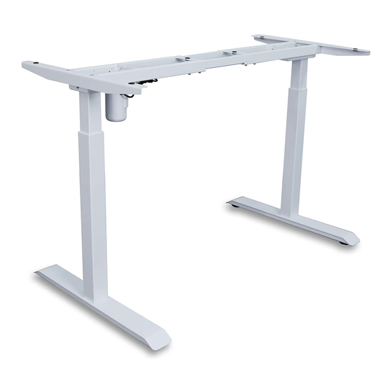
- Page 1 Electric Standing Desk User Manual Model: AIT002W...
-
Page 2: Table Of Contents
TABLE OF CONTENTS Parts and Hardware List Parts Hardware Step 1 Step 2 Step 3 Step 4 Step 5 Step 6 Step 7 Step 8 Step 9 Step 10 Step 11 Operation Guide... -
Page 3: Parts And Hardware List
PARTS AND HARDWARE LIST Component Name Crossbar Bracket Foot Margin Foot Pad Right Leg Left Leg Driveshaft Control Box Key Pad M6*14 Screw M6*12 Screw ST3.5*19 Screw ST4.8*19 Screw ST4.8*25 Screw Plastic Pad Rubber Cushion 4mm Hex Spanner Wrench Cable Tie... -
Page 4: Parts
PARTS 1 Crossbar x1 2 Bracket x2 3 Foot Margin x2 4 Foot Pad x4 5 Right Leg x1 6 Left Leg x1 7 Driveshaft x1 8 Control Box x1 9 Key Pad x1 10 Power Cord x1 HARDWARE M6*14 M6*12 ST3.5*19 ST4.8*19... -
Page 5: Step 1
STEP 1 Loosen 8 pcs M6*10screws,they were attached before packing. Adjust the beam to proper position and then tighten the screws. Tool Required:H 4mm Hex Spanner... -
Page 6: Step 3
STEP 2 Attach legs to crossbar ends using 8 pcs M6*12 screws. Tool Required:H Hardware Required: 4mm Hex Spanner M6*12screw 8PCS B Screws STEP 3 Attach foot margins to leg using 8 pcs M6*14 screws and tighten with 4mm hex spanner. Tool Required:H Hardware Required:... -
Page 7: Step 4
STEP 4 Attach brackets to each crossbar end using 4 pcs M6*12 screws. Tool Required:H Hardware Required: M6*12 screw 4pcs B Screws 4mm Hex Spanner STEP 5 Loosen the left nut from the driveshaft using wrench.Turn the left nut counterclockwise to remove it from the driveshaft.Keep the plastic grommet inside the left nut. -
Page 8: Step 6
STEP 6 Insert the left nut and plastic grommet into the right leg. Pay atten- tion to the insert direction.Push the driveshaft all the way in. Turn the left nut clockwise to firmly lock the driveshaft in place. Leave a small gap(about 0.2in) between the left nut and the right leg so they won't block the driveshaft when it turns. -
Page 9: Step 8
STEP 8 Put rubber cushions and plastic pads on the side brackets and the crossbar. Hardware Required: Plastic Pad Rubber Cushion F & G STEP 9 Attach the brackets and the crossbar to the table top using 6 pcs ST4.8*25 screws. Tool Required:... -
Page 10: Step 10
STEP 10 Attach the control box using 2 pcs ST4.8*19 screws,then attach the keypad to the table top using 2 pcs ST3.5*19 screws. Tool Required: ST4.8*19 Screw 2pcs Drill / Driver Hardware Required: C & D Screws ST3.5*19 Screw 2pcs... -
Page 11: Step 11
STEP 11 Plug cables from the motor to the control box and cable from the keypad. -
Page 12: Operation Guide
Operation Guide Activating & Troubleshooting You will need to activate the memory keypad once the desk is fully assembled, Side note : if the frame doesn’t seem to be working properly, rest assured that most issues can be fixed using the exact same activation process. 1.If the handset locked, first step is unlock.
Need help?
Do you have a question about the AIT002W and is the answer not in the manual?
Questions and answers