Table of Contents
Advertisement
Advertisement
Table of Contents

Subscribe to Our Youtube Channel
Related Manuals for aiTerminal AIT001G


Summary of Contents for aiTerminal AIT001G
- Page 1 Electric Standing Desk User Manual Model: AIT001G...
-
Page 2: Table Of Contents
TABLE OF CONTENTS Parts and Hardware List Parts Hardware Step 1 Step 2 Step 3 Step 4 Step 5 Step 6 Step 7 Operation Guide... -
Page 3: Parts And Hardware List
PARTS AND HARDWARE LIST Component Name Foot Pad Foot Margin Bracket Legs Cross Bar Control Box Key Pad M6*12 Screw M6*14 Screw ST3.5*19 Screw ST4.8*19 Screw ST4.8*25 Screw Rubber Cushion Plastic Pad 4mm Hex Spanner Cable Tie... -
Page 4: Parts
PARTS 1 Foot Pad x4 3 Bracket x2 4 Legs x2 2 Foot Margin x2 5 Crossbar x1 6 Control Box x 1 7 Keypad x1 HARDWARE M6*12 M6*14 ST3.5*19 ST4.8*19 ST4.8*25 Screw x 12 Screw x8 Screw x 2 Screw x 2 Screw x 6 Plastic Pad x6... -
Page 5: Step 1
STEP 1 Loosen 8 pcs M6*10screws,they were attached before packing. Adjust the crossbar to proper position and then tighten the 8 pcs screws. Tool Required:H 4mm Hex Spanner M6*10 screw 8 pcs... -
Page 6: Step 3
STEP 2 Attach legs to crossbar ends using 8 pcs M6*12 screws. Tool Required:H Hardware Required: M6*12screw 8 pcs 4mm Hex Spanner A Screws STEP 3 Attach foot margins to leg using 8 pcs M6*14 screws and tighten with 4mm hex spanner. Tool Required:H Hardware Required:... -
Page 7: Step 4
STEP 4 Attach brackets to each crossbar end using 4 pcs M6*12 screws. Tool Required:H Hardware Required: 4mm Hex Spanner M6*12screw 4 pcs A Screws STEP 5 Put rubber cushions and plastic pads on the side brackets and crossbar. Hardware Required : F & G Plastic Pad Rubber Cushion... -
Page 8: Step 6
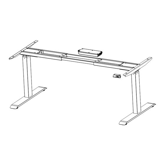
STEP 6 Attach the brackets and the crossbar to the table top using 6 pcs ST4.8*25 screws.Attach the control box using 2pcs ST4.8*19 screws Attach the keypad to the table top using 2 pcs ST3.5*19 screws. Tool Required: ST4.8*25 Screw 6 pcs Drill / Driver ST3.5*19 2 pcs Hardware Required:... -
Page 9: Step 7
STEP 7 Plug cables from two motors to the control box and cable from the keypad. -
Page 10: Operation Guide
Operation Guide Activating & Troubleshooting You will need to activate the memory keypad once the desk is fully assembled, Side note : if the frame doesn’t seem to be working properly, rest assured that most issues can be fixed using the exact same activation process. 1.If the handset locked, first step is unlock.
Need help?
Do you have a question about the AIT001G and is the answer not in the manual?
Questions and answers