Table of Contents
Advertisement
Quick Links
Advertisement
Table of Contents

Subscribe to Our Youtube Channel
Related Manuals for aiTerminal AIT004B


Summary of Contents for aiTerminal AIT004B
-
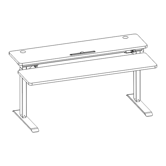
Page 1: User Manual
Electric Standing Desk User Manual Model: AIT004B... - Page 2 TABLE OF CONTENTS Parts and Hardware List Parts Hardware Step 1 Step 2 Step 3 Step 4 Step 5 Step 6 Step 7 Step 8 Step 9 Operation Guide...
-
Page 3: Table Of Contents
PARTS AND HARDWARE LIST Component Name Top Bracket Bottom Bracket Foot Left Leg Key Pad Beam Control Box Right Leg Driveshaft Table Top (1500*370*25) Table Top (1500*400*25) M6*12 Screw (Black) M6*12 Screw (Silver) M6*16 Screw ST3.5*19 Screw ST4.8*19 Screw ST4.8*25 Screw Plastic Rubber Cushion Gasket 6... -
Page 4: Top Bracket
PARTS 1 Top Bracket x2 2 Bottom Bracket x2 3 Foot x2 4 Left Leg x1 5 Key Pad x1 6 Beam x1 7 Control Box x1 8 Right Leg x1 9 Driveshaft x1 10 Table Top 11 Table Top (1500*370*25) (1500*400*25) HARDWARE... -
Page 5: 4Mm Hex Spanner
STEP 1 Attach left leg to the beam using 4pcs M6*12 screws(silver). Tool Required:J Hardware Required: B Screws M6*12 screws 4 pcs 4mm Hex Spanner STEP 2 Insert hex bar of driving rod into right leg and using spanner to loosen nut on the driving rod to allow the length of the hexagon rod to be stretched. -
Page 6: K 5Mm Hex Spanner
STEP 3 Attach right leg along with driving rod to the beam using 4 pcs M6*12 screws,both ends of the drive rod can not interfere with the crossbeam and right leg. Tool Required:J Hardware Required: B Screws M6*12 screws (silver) 4mm Hex Spanner 4 pcs STEP 4... - Page 7 STEP 5 Install the top bracket on the beam using 4 pcs M6*12 screws (silver) and put 6 rubber cushions into the each hole site of brackets and beam. Tool Required:J Hardware Required: B Screws(silver) M6*12 4pcs 4mm Hex Spanner Rubber Cushion 6 pcs Plastic 6 pcs G &...
- Page 8 STEP 7 Install the top bracket with 8 pcs M6*12 screws(black) and put 4 rubber cushions into the each hole site of brackets and insert the plastic into the rubber pad from the bottom. Rubber Cushion 4 pcs Plastic 4 pcs M6*12 8 pcs (Black) Tool Required:J...
-
Page 9: M Cable Tie
STEP 9 Connect the motors and handset to the control box,installation completed.Use cable tie to hold the spare cable in place. Hardware Required:M Cable Tie... -
Page 10: Operation Guide
Operation Guide Activating & Troubleshooting You will need to activate the memory keypad once the desk is fully assembled, Side note : if the frame doesn’t seem to be working properly, rest assured that most issues can be fixed using the exact same activation process. 1.If the handset locked, first step is unlock.
Need help?
Do you have a question about the AIT004B and is the answer not in the manual?
Questions and answers