Table of Contents
Advertisement
Quick Links
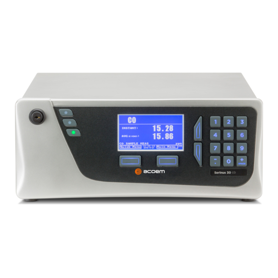
Serinus® 30
Carbon Monoxide
ACOEM Ecotech
1492 Ferntree Gully Road Knoxfield VIC 3180
Melbourne Australia +61 3 9730 7800 info.au@acoem.com ecotech.com
Manual subject to change without notice. Images used are for illustrative purposes only. Ecotech & Serinus are trademarks or registered trademarks
of Ecotech Pty Ltd in the United States and/or other countries. © 2021 Ecotech Pty Ltd. All Rights Reserved.
Analyser
User Manual
Version: 3.3
Advertisement
Table of Contents
Troubleshooting

Related Manuals for Ecotech Acoem Serinus 30


Summary of Contents for Ecotech Acoem Serinus 30
- Page 1 Melbourne Australia +61 3 9730 7800 info.au@acoem.com ecotech.com Manual subject to change without notice. Images used are for illustrative purposes only. Ecotech & Serinus are trademarks or registered trademarks of Ecotech Pty Ltd in the United States and/or other countries. © 2021 Ecotech Pty Ltd. All Rights Reserved.
- Page 2 Ser in u s ® 30 U ser M an u al 3 .3 This page is intentionally blank. Page 2...
-
Page 3: Table Of Contents
Table of Contents Table of Contents ..............................3 Manufacturer’s Statement ............................ 12 Notice ..................................12 Safety Information ..............................13 Warranty ................................15 Service & Repairs ..............................16 Product Compliance and Approvals ........................17 Manual Revision History ............................18 Introduction ........................... 21 Description .............................. - Page 4 Ser in u s ® 30 U ser M an u al 3 .3 Warm-Up ..............................51 Measurement ............................51 General Operation Information ........................ 52 3.3.1 Keypad & Display........................52 3.3.2 Home Screen ..........................54 Menus & Screens ............................56 3.4.1 Quick Menu ..........................
- Page 5 4.4.1 Analog Outputs .......................... 99 4.4.2 Analog Inputs ........................... 100 4.4.3 Digital Status Inputs ......................... 100 4.4.4 Digital Status Outputs ......................100 Logging Data ............................101 4.5.1 Configure Instrument Internal Logging ..................101 Using Airodis Software to Download Data ....................102 4.6.1 Connecting the Instrument to a PC ..................
- Page 6 Noisy/Unstable Readings ........................163 Cell Temperature Failure ........................164 Mirror Temperature Failure ........................165 USB Memory Stick Failure........................166 Ecotech Service Support Files ......................... 167 Optional Extras........................170 Dual Sample Filter (PN: E020100) ......................170 Network Port (PN: E020101)........................170 8.2.1...
- Page 7 Figure 15 – Pressure Sensor PCA ..........................32 Figure 16 – Heater and Thermistor ..........................33 Figure 17 – Orifice and Sintered Filter ......................... 33 Figure 18 – Ecotech Tubing ............................33 Figure 19 – Rear Panel ..............................34 Figure 20 – Power ON/OFF Switch ..........................35 Figure 21 –...
- Page 8 Ser in u s ® 30 U ser M an u al 3 .3 Figure 29 – Turn ON Power Switch ..........................42 Figure 30 – Dust Plugs ..............................43 Figure 31 – Remove Nut ............................... 43 Figure 32 – Ferrules Correct Orientation ........................43 Figure 33 –...
- Page 9 Figure 81 – Example of Network Menu Setup ......................97 Figure 82 – Port Forwarding Example .......................... 97 Figure 83 – LAN Network Set-Up (Airodis) ........................98 Figure 84 – WAN Network Set-Up (Airodis) ......................... 98 Figure 85 – 25 Pin Rear Panel PCA (Default Jumpers Highlighted) ................100 Figure 86 –...
- Page 10 Ser in u s ® 30 U ser M an u al 3 .3 Figure 133 – Remove Filter Casing and Filter ......................145 Figure 134 – Remove Kynar Nut ..........................146 Figure 135 – Leak Test Jig on Exhaust Port ......................... 147 Figure 136 –...
- Page 11 Table 24 – Spare Parts List (Miscellaneous) ....................... 190 Table 25 – Spare Parts List (Shipping) ........................190 Table 26 – Spare Parts List (External CO Sensor) ...................... 191 Table 27 – Packet Format ............................202 Table 28 – Example: Primary Gas Request ......................... 202 Table 29 –...
-
Page 12: Manufacturer's Statement
Thank you for selecting the Ecotech Serinus® 30 Carbon Monoxide Analyser. The Serinus series is the next generation of Ecotech designed and manufactured gas analysers. The Serinus 30 will perform CO measurements over a range of 0 - 200 ppm with a lower detectable limit of 40 ppb. -
Page 13: Safety Information
These symbols will also be found throughout this manual to indicate relevant safety messages. Note: Notes are used throughout this manual to indicate additional information regarding a particular part or process. If the equipment is used for purposes not specified by Ecotech, the protection provided by this equipment may be impaired. Foreword... - Page 14 Replacing Parts Replacement of any part should only be carried out by qualified personnel, using only parts specified by Ecotech, as these parts meet stringent Ecotech quality. Mains Supply Cord Do not replace the detachable mains supply cord with an inadequately rated cord. Any mains supply cord that is used with the instrument must comply with the safety requirements (250 V/10 A minimum requirement).
-
Page 15: Warranty
Warranty This product has been manufactured in an ISO 9001 facility with care and attention to quality. The product is subject to a 24-month warranty on parts and labour from date of shipment. The warranty period commences when the product is shipped from the factory. Lamps, filters and other consumable items are not covered by this warranty. -
Page 16: Service & Repairs
Please dial +61 3 9730 7800 if calling from outside of Australia. Please contact Ecotech and obtain a Return Material Authorisation (RMA) number before sending any equipment back to the factory. This allows us to track and schedule service work and to expedite customer service. -
Page 17: Product Compliance And Approvals
Product Compliance and Approvals The Serinus® 30 Carbon Monoxide Analyser, as manufactured by Ecotech Pty Ltd, complies with the essential requirements of the directives listed below (including CE compliance). The respective standards have been applied: Low Voltage Directive (LVD) Directive 2014/35/EU... -
Page 18: Manual Revision History
Any information that cannot be found within this manual can be obtained by contacting Ecotech. This manual uses cross reference links extensively throughout this manual. The hot keys below will greatly reduce the amount of time scrolling between references: ... - Page 19 Edition Date Summary July 2012 New chassis Update menu system Add Bluetooth menu Serinus Remote Android App Rack mount procedure update Analog output calibration March 2013 Update of manual drawings, pictures and content. Format updated. November 2013 Formatting updates Addition of Airodis installation steps December 2014 Auto-Ranging Power Supply added Main Controller and Rear Panel PCAs changed.
- Page 20 Ser in u s ® 30 U ser M an u al 3 .3 This page is intentionally blank. Page 20...
-
Page 21: Introduction
1. Introduction 1.1 Description The Ecotech Serinus 30 Carbon Monoxide Analyser uses Non-Dispersive Infrared Spectrophotometry (NDIR) technology to measure CO in ambient air, in the range of 0 - 200 ppm. The U.S. EPA has designated the Serinus 30 Carbon Monoxide Analyser as a reference method and TÜV has designated it as an EN approved instrument. -
Page 22: Calibration
0 - 40 °C (32 - 104 °F) Relative Humidity: 10 - 80% (non-condensing) Pollution Degree: Sample Pressure Dependence: 5% change in pressure produces less than a 1% change in reading Maximum altitude 2000 m above sea level For higher altitude contact Ecotech for support/assistance. Page 22... -
Page 23: Communications
1.2.6 Communications Analog Output Three menu selectable current or voltage analog outputs. Current output of 0 - 20 mA, 2 - 20 mA or 4 - 20 mA. Voltage output of 0 - 5 V, with menu selectable zero offset of 0 V, 0.25 V or 0.5 V. ... -
Page 24: Nomenclature
Ser in u s ® 30 U ser M an u al 3 .3 EN approval MCERTS (MC100166/07) Australian Standard (AS 3580.7.1-2011) Russian approval (56262-14) French approval (LSCQA) Ukraine approval (12/3/B/24/295-17) Chinese Pattern Approval (JJF1364-2012) ... -
Page 25: Background/Theory
following the prompts. The Bootloader enables various low level recovery tools, including updating the firmware from a USB stick. Printed Circuit Assembly. An electronic circuit mounted on a printed circuit board to perform a specific electronic function. Infrared. The region of the optical spectrum with a wavelength of around 4.7 microns. -
Page 26: Kalman Filter Theory
Ser in u s ® 30 U ser M an u al 3 .3 Figure 1 – Measurement Cell Theory A gas filter correlation wheel is combined with this system. This wheel contains three parts to increase measurement accuracy: CO, N and the mask. -
Page 27: Instrument Description
1.5 Instrument Description The major components of the Serinus 30 are described below: Figure 3 – Internal Components Diagram 1.5.1 Calibration Valve Manifold Refer to Figure 3 for the location of calibration valve manifold. The calibration valve manifold switches between sample, calibration and background gas. Figure 4 –... -
Page 28: Sample Filter Holder
Ser in u s ® 30 U ser M an u al 3 .3 1.5.2 Sample Filter Holder Refer to Figure 3 for the location of sample filter holder. Within the sample filter holder is a particulate filter. The particulate filter is a Teflon 5-micron (µm) filter with a diameter of 47 mm. This filter prevents all particles larger than 5 µm from entering the measurement system that could interfere with sample measurement. -
Page 29: Measurement Cell
1.5.4 Measurement Cell Refer to Figure 3 for the location of measurement cell. The measurement cell consists of the following components: Figure 7 – Measurement Cell 1.5.4.1 Cell Refer to Figure 7 for the location of cell. The cell contains five mirrors that form a five-meter folded path length through the cell. -
Page 30: Figure 9 - Ir Source
Ser in u s ® 30 U ser M an u al 3 .3 IR Source The IR source emits broadband infrared radiation that irradiates the filter in the correlation wheel. Figure 9 – IR Source Gas Filter Correlation Wheel Assembly The gas filter correlation wheel contains three segments: a N filled sapphire chamber, a CO filled sapphire chamber and a mask. -
Page 31: Figure 11 - Detector Assembly
Motor Assembly The motor that drives the correlation wheel is a 12 VDC Brushless motor. 1.5.4.3 Detector Assembly Refer to Figure 7 for the location of detector assembly. The detector assembly consists of the following: Figure 11 – Detector Assembly Narrow-Bandpass Filter The narrow bandpass filter allows only the CO sensitive portion of the IR radiation to pass through to the IR detector (4.7 microns) reducing noise and interference. -
Page 32: Figure 14 - Co Detector Pca
Ser in u s ® 30 U ser M an u al 3 .3 CO Detector PCA The detector PCA amplifies the signal from the IR detector and it includes the trim pot to adjust the detector gain. Figure 14 – CO Detector PCA 1.5.4.4 Pressure Sensor PCA Refer to Figure 7 for the location of pressure sensor PCA. -
Page 33: Main Controller Pca
1.5.6 Pneumatic Tubing The pneumatic tubing inside this instrument is specially designed for use in Ecotech Serinus instruments. It has the flexibility of Silicone tubing with the added inner sheath of PVDF to prevent contamination of the sample. Care should be taken when removing and inserting the tubing into the barbed fittings. -
Page 34: Rear Panel
Ser in u s ® 30 U ser M an u al 3 .3 1.5.7 Rear Panel Figure 19 – Rear Panel 1.5.7.1 Rear Panel PCA Refer to Figure 19 for the location of rear panel PCA. The rear panel PCA contains all the connections for external communications, including analog input, analog output, digital inputs, digital outputs, RS232, USB, and TCP/IP network connection (optional). -
Page 35: Communications
1.5.8 Communications Communication between the instrument and either a data logger, laptop or network can be performed with the following communication connections located on the rear panel (refer to Figure 21). These connections can be used for downloading data, onsite diagnostics, maintenance and firmware upgrades. - Page 36 Ser in u s ® 30 U ser M an u al 3 .3 Analog Inputs The instrument is also equipped with three analog voltage inputs (0 - 5 VDC CAT 1) with resolution of 15 bits plus polarity. CAUTION Exceeding these voltages can permanently damage the instrument and void the warranty.
-
Page 37: Installation/Decommission
Packaging The Serinus® 30 is transported in packaging specifically designed to minimise the effects of shock and vibration during transportation. Ecotech recommends that the packaging be kept if there is a likelihood that the instrument is going to be relocated. -
Page 38: Figure 22 - Received Item
Ser in u s ® 30 U ser M an u al 3 .3 Figure 22 – Received Item Page 38... -
Page 39: Figure 23 - Opening The Instrument - 1
Opening the Instrument Check the interior of the instrument with the following steps: 1. Refer to Figure 23. Remove the thumb screws located on the rear panel. Figure 23 – Opening the Instrument – 1 2. Refer to Figure 24. Unlocked the slam lock using keys provided with instrument. Figure 24 –... -
Page 40: Installation Notes
Ser in u s ® 30 U ser M an u al 3 .3 4. Refer to Figure 26. To completely remove the lid, slide the lid backwards until the rollers line up with the gaps in the track and lift the lid upwards to remove from the instrument. Figure 26 –... -
Page 41: Instrument Set-Up
Note: The power ON/OFF switch is accessible from the rear of the instrument only. Install the instrument so that the ON/OFF power switch is accessible. 2.3 Instrument Set-Up After installing the instrument, the following procedures should be followed to ready the instrument for monitoring: Figure 27 –... -
Page 42: Pneumatic Connections
Ser in u s ® 30 U ser M an u al 3 .3 The mains power outlet must be protected by an earth leakage protection circuit. Refer to Figure 28. Connect the instrument’s power cord into the instrument and mains power outlet. -
Page 43: Figure 30 - Dust Plugs
Procedure 1. Refer to Figure 30. Remove all the dust plugs. Figure 30 – Dust Plugs 2. Refer to Figure 31. Remove the sample port nut. Figure 31 – Remove Nut 3. Inspect the ferrules inside the nut for correct orientation. Figure 32 –... -
Page 44: Figure 33 - Replace Nut Loosely
Ser in u s ® 30 U ser M an u al 3 .3 4. Replace the nut loosely, only 2 or 3 threads, on the sample port. Figure 33 – Replace Nut Loosely 5. Push the tubing into the end of the nut until you hit the tube stop inside the fitting. Figure 34 –... -
Page 45: Communications Connections
The calibration port can be connected to the span/zero sources. It is recommended that a gas dilution calibrator (Ecotech’s Serinus Cal 1000, 2000 or 3000) be used with a cylinder of carbon monoxide (CO) to deliver precise concentrations of CO. -
Page 46: Instrument Set-Up
Ser in u s ® 30 U ser M an u al 3 .3 2.3.4 Instrument Set-Up 1. Refer to Figure 36. Open the lid and make sure the USB memory stick is installed. Figure 36 – Installation of USB Memory Stick 2. -
Page 47: Epa Reference Set-Up
20 - 30 °C Line Voltage 105 - 125 VAC, 60 Hz Pump Ecotech optional internal or external pump Filter Factory setup to meet requirement: Instrument Settings If the units in the measurement menu are changed from volumetric to gravimetric (or gravimetric to volumetric) the instrument must be re-calibrated. -
Page 48: Type Approval Set-Up
Ser in u s ® 30 U ser M an u al 3 .3 Measurement Settings Menu Background Interval: 24 hrs Calibration Menu Span Comp: Disabled Diagnostics Menu Press/Temp/Flow Comp: Diagnostic Mode: Operate Control loop: Enabled The instrument must be operated and maintained in accordance with this User Manual. The Serinus 30 analyser is designated U.S. -
Page 49: Transporting/Storage
Diagnostics Menu Press/Temp/Flow Comp: Diagnostic mode: Operate Control Loop: Enabled 2.6 Transporting/Storage Transporting the instrument should be done with great care. It is recommended that the packaging the instrument was delivered in should be used when transporting or storing. When transporting or storing the instrument the following points should be followed: 1. -
Page 50: Figure 40 - Packing Instruction
Note: Ecotech recommended to use the same packing material in which instrument is delivered. 10. The instrument is now ready for long term storage or transportation. -
Page 51: Operation
3. Operation 3.1 Warm-Up When the instrument is first turned ON it must go through a period of adjustment and calibration. No measurements are taken during this warm-up period. The following activities occur during warm-up: Auto Ref. Adjust Adjusts the reference voltage and internal trim pot setting Auto Zero Adjust Adjusts the zero offset Heat CO Scrubber... -
Page 52: General Operation Information
Ser in u s ® 30 U ser M an u al 3 .3 3.3 General Operation Information 3.3.1 Keypad & Display The instrument is operated with the use of four sets of buttons: Figure 41 – Front Panel Selection Buttons (1) The selection buttons will perform the function specified directly above it on the screen. - Page 53 Button Function 5, J, K, L, j, k, l 6, M, N, O, m, n, o 7, P, Q, R, S, p, q, r, s 8, T, U, V, t, u, v 9, W, X, Y, Z, w, x, y, z 0 or space, underline ) and key ( .
-
Page 54: Home Screen
Ser in u s ® 30 U ser M an u al 3 .3 3.3.2 Home Screen The home screen is composed of seven parts: readings (1), error/status line (2), instrument activity line (3), selection buttons (4), time/date (5), concentration units (6) and USB status (7). Figure 42 –... - Page 55 Concentration Units (6) The instrument units are displayed in the bottom right corner of the display. USB Detection (7) A USB symbol will be displayed in the bottom right corner when the USB memory stick is plugged in (the USB socket is behind the front panel). If the USB symbol is not shown the USB memory stick should be inserted.
-
Page 56: Menus & Screens
Ser in u s ® 30 U ser M an u al 3 .3 3.4 Menus & Screens Status Menu Temperature Menu Analyser State Menu Pressure & Flow Menu General Settings Menu Voltage Menu Measurement Settings Menu Pressure Calibration Menu Calibration Menu Flow Calibration Menu... -
Page 57: Quick Menu
The menu system is divided into two sections selectable from the Home Screen: The Quick Menu and the Main Menu. The Quick Menu contains all information and operations necessary during scheduled maintenance visits. The Main Menu contains all fields that are accessible to the users. It provides information on component failures and measurement parameters as well as editable fields and test procedures. -
Page 58: Main Menu
Ser in u s ® 30 U ser M an u al 3 .3 Instrument Gain This is a multiplication factor which is used to adjust the concentration measurement to the appropriate level (set by performing a Span Calibrate CO). This should be recorded after each calibration in the station log book. -
Page 59: Analyser State Menu
Model This field will display the instrument model (e.g. Serinus 30). Nominal Range The measurement range of the instrument. Ecotech ID The Ecotech ID number. Serial No. The main controller PCA serial number. Board Revision The main controller PCA version. -
Page 60: Status Menu
Ser in u s ® 30 U ser M an u al 3 .3 3.4.4 Status Menu Main Menu → Analyser State Menu → Status Menu Status Menu presents a list of the current Pass/Fail status of the main components. During warm-up, the status of some parameters will be a dashed line. -
Page 61: Temperature Menu
Diagnostic Mode Error if the electronics are in Diagnostic Mode (refer to Section 3.4.14). Diagnostic PTF Comp Error if the Pres/Temp/Flow Comp. is disabled (refer to Section 3.4.14). Diagnostic Control Error if the control loop is disabled (refer to Section 3.4.14). Valve Manual Control Error if the valves have been placed in manual control mode (refer to Section 3.4.17). -
Page 62: Pressure & Flow Menu
Ser in u s ® 30 U ser M an u al 3 .3 Temperature Units The current temperature units of the instrument (Celsius, Fahrenheit or Kelvin). Set Point (CELL) The temperature set point of the measurement cell. The factory default is 50 °C. -
Page 63: Voltage Menu
3.4.7 Voltage Menu Main Menu → Analyser State Menu → Voltage Menu Figure 49 – Voltage Menu Screen IR Source The drive voltage of the IR source 5 V ± 0.5 V. Conc. Voltage (RAW) Voltage from the sensor proportional to the detected signal from the measurement cell. -
Page 64: General Settings Menu
Ser in u s ® 30 U ser M an u al 3 .3 3.4.8 General Settings Menu Main Menu → General Settings Menu Figure 50 – General Settings Menu Screen Decimal Places Select the number of decimal places (0 - 5) used for the concentration displayed on the home screen. -
Page 65: Measurement Settings Menu
3.4.9 Measurement Settings Menu Main Menu → Measurement Settings Menu Figure 51 – Measurement Settings Menu Screen Average Period Set the time period over which the average will be calculated: Minutes (1, 2, 3, 4, 5, 6, 10, 12, 15, 20 or 30) or hours (1, 2, 4, 6, 8, 12 or 24) or rolling hourly averages over the last (4 or 8) hours. -
Page 66: Calibration Menu
Ser in u s ® 30 U ser M an u al 3 .3 Time Edit and display the time that the next background will run. The time is set using a 24-hour clock. [Backgrounds] Repeat Defines an interval value for the repeat of the background based on the Units selected. - Page 67 Zero Source Select whether the instrument will sample from the external calibration port or from the internal zero source when zero gas is requested. Cycle Time The duration of each Cal. Mode (span and zero) when performing Cycle Mode (refer to Section 3.4.10.1) or Cal. Type is set to Timed. (refer to Section 3.4.10.2) Span Calibrate CO This field is used to perform a span calibration and should be only used...
-
Page 68: Pressure Calibration Menu
Ser in u s ® 30 U ser M an u al 3 .3 3.4.10.2 Timed Mode These items appear in the Calibration Menu when Cal. Type is set to Timed. Date Enter the date for the next calibration to start. Time Enter the time that calibration will be performed. -
Page 69: Flow Calibration Menu (Option)
Ambient The current ambient pressure. Cell The current pressure in the measurement cell. The current measurement cell pressure displayed as a raw voltage. Vacuum Cal Mode Defaults to Off. When turned On, the valves will be set to the same state as during a Vacuum Set Pt. -
Page 70: Service Menu
Ser in u s ® 30 U ser M an u al 3 .3 Pump Control Set to MANUAL to disable the automatic pump control. AUTO allows the flow PID to modify the pump coarse and fine settings. START will transition to AUTO after one second. -
Page 71: Diagnostics Menu
Safely Remove USB Stick This command must be activated to safely remove the USB memory stick. System Restart Activating this will restart the instrument. 3.4.14 Diagnostics Menu Main Menu → Service Menu → Diagnostics Menu Figure 56 – Diagnostics Menu Screen Digital Pots Menu Refer to Section 3.4.15. -
Page 72: Figure 57 - Digital Pots Menu Screen
Ser in u s ® 30 U ser M an u al 3 .3 Figure 57 – Digital Pots Menu Screen PGA Gain 1 - 128 Displays the gain of the PGA. Input Pot 180 - 230 Reduces the raw signal to measurable level. The concentration voltage measured by the analog to Conc. -
Page 73: Internal Pump Menu (Option)
Preamp: Injects an artificial test signal into the Preamplifier mounted on the Measurement Cell to verify that the Preamplifier, cabling and electronic circuitry on the main controller PCA is operating correctly. When in this Diagnostic Mode, adjust the Test Meas Pot from 0 - 255. This will produce a change in the concentration voltage as well as the indicated gas concentration. -
Page 74: Valve Menu
Ser in u s ® 30 U ser M an u al 3 .3 3.4.17 Valve Menu Main Menu → Service Menu → Diagnostics Menu → Valve Menu The Valve Menu allows the user to observe the instrument controlled switching of the valves. If the valve is On it means the valve is energised. -
Page 75: Tests Menu
3.4.18 Tests Menu Main Menu → Service Menu → Diagnostics Menu → Tests Menu Figure 60 – Tests Menu Screen Screen Test Performs a screen test by drawing lines and images on the screen so that the operator can determine if there are any faults in the screen. -
Page 76: Digital Output Test Menu
Ser in u s ® 30 U ser M an u al 3 .3 3.4.20 Digital Output Test Menu Main Menu → Service Menu → Diagnostics Menu → Tests Menu → Digital Output Test Menu Figure 62 – Digital Output Test Menu Screen Automated Test When started will automatically step through each output, turning it On and Off. - Page 77 Instrument Gain A multiplication factor used to adjust the concentration measurement to the appropriate level (set at calibration). Zero Offset CO This field displays the offset created from a zero calibration. This is the concentration measured from zero air and is subtracted from all readings.
-
Page 78: Communications Menu
Ser in u s ® 30 U ser M an u al 3 .3 3.4.22 Communications Menu Main Menu → Communications Menu Configures how the instrument communicates with external instrumentation and data loggers. Figure 64 – Communications Menu Screen Data Logging Menu Refer to Section 3.4.23. -
Page 79: Serial Communication Menu
Data Log Interval Displays the interval at which the data is saved to the USB memory stick. Selecting a 1 sec interval may result in occasional measurements not being logged or slow response to serial commands. Cal. Log Interval When enabled displays the interval at which the data is saved to the USB memory stick for the calibration time period. -
Page 80: Analog Input Menu
9600, 14400, 19200, 38400 or 115200). Protocol Sets the protocol used for this serial port (Advanced, ModBus, EC9800 or Bayern-Hessen). This must be set to Advanced for Ecotech supplied software. Endian Select Little or Big endian mode for ModBus protocol. [Modbus Protocol] 3.4.25... -
Page 81: Analog Output Menu
Offset This value will be added to the above calculation. Continuing the example in the multiplier description, the offset should be set to -40, so that a voltage of 0 V will be recorded as -40 °C. Reading The current reading from the analog input, after the multiplier and offset are applied. - Page 82 Ser in u s ® 30 U ser M an u al 3 .3 Over-Ranging Set to Enabled or Disabled to turn the over-ranging feature On or Off. Over Range This field is only editable when Over-Ranging is set to Enabled.
-
Page 83: Digital Input Menu
3.4.27 Digital Input Menu Main Menu → Communications Menu → Digital Input Menu This menu is used to remotely trigger zero and span calibrations. This is done by assigning the eight digital inputs with one of the following commands. Figure 69 – Digital Input Menu Screen DI N (Pin X) Associates an action with a digital input. -
Page 84: Digital Output Menu
Ser in u s ® 30 U ser M an u al 3 .3 3.4.28 Digital Output Menu Main Menu → Communications Menu → Digital Output Menu This allows the instrument to trigger external alarms in response to certain events. There are eight different pins available, which will be set high during an associated event: Figure 70 –... -
Page 85: Network Menu (Option)
Digital Output State Description Span Performing a span check. Zero Performing a zero check. System Fault Any system fault (the red light is ON). Maintenance Mode User has activated maintenance mode. Over Range AO 0 Over range for the analog output when channel 0 is active. - Page 86 The default ID setting is Serinus(Ecotech ID). The word Serinus is always the first part of the name and cannot be edited. The second part is the Ecotech ID. Adaptor is in DHCP mode In this mode the instrument will ask for its network parameters from a DHCP server on your network.
-
Page 87: Bluetooth Menu
The default ID setting is Serinus(Ecotech ID). The word Serinus is always the first part of the name and cannot be edited. The second part is the Ecotech ID. 3.4.31 Trend Display Menu Main Menu → Trend Display Menu Figure 73 –... -
Page 88: Chart
Ser in u s ® 30 U ser M an u al 3 .3 Name Displays the name of the Parameter the user has selected. Parameter Allows the user to select any loggable (refer to Table 33) parameter to graph on the trend display. Autoscale Autoscale can be ON or OFF. - Page 89 Chart X-Axis (3 & 4) (3) Displays the time stamp for the oldest data point (left hand side). (4) Displays the time stamp for the newest data point (right hand side) or if the cursor is active it displays the current cursor data point time stamp. Chart Y-Axis (5 &...
-
Page 90: Advanced Menu
Ser in u s ® 30 U ser M an u al 3 .3 3.4.33 Advanced Menu This menu is accessed via a different method than the other menus. From the Home Screen press the ( . ̅)99( following keys: SPACE This menu contains technical settings, diagnostics and factory hardware installations. -
Page 91: Hardware Menu
3.4.34 Hardware Menu Advanced Menu → Hardware Menu This menu contains factory hardware installations. If the user reset to factory defaults, then they may need to revisit this menu to enable their installed optional features. Figure 76 – Hardware Menu Screen Model Select the instrument model. -
Page 92: Parameter Display Menu
Ser in u s ® 30 U ser M an u al 3 .3 3.4.35 Parameter Display Menu Advanced Menu → Parameter Display Menu Used to display a parameter in real-time on the screen (refer to Table 33 for a full list of parameters). Figure 77 –... -
Page 93: Communications
USB, 25 pin digital/analog input/output, TCP/IP network (optional) and Bluetooth). A demonstration version of Ecotech’s Airodis software is included with the instrument, enabling basic data downloads and remote operation from a PC running a supported MS Windows operating system. The full version of Airodis is available separately and includes automated data collection, data validation and complex reporting by multiple users. -
Page 94: Usb Communication
Figure 79 – Multidrop RS232 Cable Example 4.2 USB Communication This is ideal for irregular connection to a laptop running Ecotech’s Airodis software to download logged data and remotely control the instrument. Due to the nature of USB, this is a less reliable permanent connection as external electrical noise can cause USB disconnection errors on a data logger. -
Page 95: Tcp/Ip Network Communication (Optional)
4.3 TCP/IP Network Communication (Optional) Instruments with the optional network port installed can be accessed using a TCP/IP connection. Figure 80 shows examples of some possible configurations for remote access. Figure 80 – Example of Typical Network Setups Communications Page 95... -
Page 96: Reading Network Port Setup
Ser in u s ® 30 U ser M an u al 3 .3 Note: In Figure 80 all the IP addresses are taken as an example. The WAN IP addresses are normally provided by your ISP. Whereas, the LAN IP addresses can be set manually to any range which is within the subnet of the Modem/Router/Switch. -
Page 97: Port Forwarding On Remote Modem/Router Setup
6. Select - Protocol → Advanced - Accept. Figure 81 – Example of Network Menu Setup 7. Once completed, use the power switch on the rear of the instrument to turn the power OFF. Leave the instrument OFF for 10 seconds before turning the power back ON. Note: Manually perform a hardware power cycle every time the IP address is changed for it to take effect. -
Page 98: Airodis Setup To Communicate With Serinus
Ser in u s ® 30 U ser M an u al 3 .3 4.3.4 Airodis Setup to Communicate with Serinus Below is an example of Airodis setup for a LAN network. Ensure the IP address is set to the same as on the instrument Network Menu. -
Page 99: Analog And Digital Communication
4.4 Analog and Digital Communication The 25 Pin analog and digital I/O port on the rear panel of the instrument sends and receives analog and digital signals to other devices. These signals are commonly used to activate gas calibrators or for warning alarms. -
Page 100: Analog Inputs
Ser in u s ® 30 U ser M an u al 3 .3 4.4.2 Analog Inputs The instrument is also equipped with three analog inputs with resolution of 15 bits plus polarity, accepting a voltage between 0 - 5 V. These go directly to the microprocessor and should be protected to ensure static/high voltage does damage the main controller PCA (instrument warranty does not cover damage from external inputs). -
Page 101: Logging Data
Figure 86 – Analog & Digital I/O Individual Pin Descriptions CAUTION The analog and digital inputs and outputs are rated to CAT I. Exceeding 12 VDC or drawing greater than 400 mA on a single output or a total greater than 2 A across the eight outputs can permanently damage the instrument and void the warranty. -
Page 102: Using Airodis Software To Download Data
Ser in u s ® 30 U ser M an u al 3 .3 4. Edit - (Change one of the storage locations “Parameter 1 - 12” to the parameter number user wishes to log) - Accept. 4.5.1.2 Data Log – Text Procedure 1. -
Page 103: Figure 88 - Update Driver Popup
When prompted where to search for the driver, select “Browse my computer for driver software”. Figure 88 – Update Driver Popup The Serinus USB driver is located on the green Ecotech resources USB stick under “\Drivers\Ecotech Analyser”. Select this directory and click Next. -
Page 104: Figure 90 - Installing Driver Confirmation Prompt
Ser in u s ® 30 U ser M an u al 3 .3 If the user receives a confirmation prompt to install the driver, select Install. Figure 90 – Installing Driver Confirmation Prompt If everything went smoothly, Windows will inform the user that the driver was successfully installed. Figure 91 –... -
Page 105: Installing Airodis
The user can download data from the instrument using either a full retail (paid) version of Airodis or with the demo version which is included on the green Ecotech resources USB stick. The demo version has limited functionality, but will allow the user to download and export data from up to three instruments. -
Page 106: Figure 93 - Adding A New Station
2. Start the Client, Server and Download Server by single-clicking the toggle button for each. The client may prompt to register with Ecotech or install an update. Follow the prompts if it does. 3. Once the Client application has loaded, click Home → Add Station → New Physical Station. -
Page 107: Figure 95 - Station Configuration (Channel List)
Property Description Database Name This is the name to be used for the table in the SQL database containing this station’s data. It must be unique for each station. Device ID Enter the Serial ID of the instrument. If the user is not using multidrop;... -
Page 108: Figure 96 - Error Status Notification
Ser in u s ® 30 U ser M an u al 3 .3 Figure 96 – Error Status Notification 7. Select the Data Manager tab, click download. The Download Data window will appear. Select the appropriate time period that the user wishes to download and click Download. Figure 97 –... -
Page 109: Figure 98 - Download Data Status
8. The status of the download will appear in the bottom-left corner of the window. The user can also monitor the status of the download from the Home tab. Figure 98 – Download Data Status 9. Data will become available in the data manager as it is downloaded. The user can load data for a date range by entering the start and end dates and clicking Display. -
Page 110: Figure 100 - Exporting Data
Ser in u s ® 30 U ser M an u al 3 .3 10. Data can be exported by clicking the Export function. This will allow the user to save their data in CSV format, which can be loaded into another program such as Microsoft Excel. It is also possible to copy/paste (Ctrl + C / Ctrl + V) data directly from the Airodis data manager. -
Page 111: Serinus Remote App/Bluetooth
4.7.1 Installation The Serinus Remote Application can be found in the Google Play Store by searching for Ecotech or Serinus. Once found, choose to Install the application and Open to start the application. Figure 102 – Downloading the App from Google Play Store Note: A menu containing additional features and functions can be accessed by entering the Options Menu (or similar) on the device. -
Page 112: Instrument Control
Ser in u s ® 30 U ser M an u al 3 .3 4. Input the PIN (if prompted) and press OK (refer to Section 3.4.30). Figure 103 – Bluetooth Pairing Request 5. A screen shot of the instrument’s current screen should appear on the users smartphone or tablet. To disconnect press the back key/button on the device. -
Page 113: Figure 104 - Showing Or Hiding The Numpad
Figure 104 – Showing or Hiding the NumPad Left-hand Section of the Screen Swiping from left to right brings up a list of available analysers (swipe from right to left to hide the instrument list). Figure 105 – Switching Analysers Back Button This button will enable the user to return to the selection screen, allowing connection to a different instrument. -
Page 114: Real-Time Plot
Ser in u s ® 30 U ser M an u al 3 .3 4.7.4 Real-Time Plot Allows the user to view real-time plotting of up to four parameters at the same time. The user can also scroll from left to right, top to bottom or zoom in and out on the plot by swiping/pinching. Once the plot is zoomed or scrolled, it enters into Observer Mode, meaning that auto-scaling is suspended. -
Page 115: Download
4.7.5 Download Download logged data from the USB memory stick inside the instrument. All data logged by the instrument to the USB memory stick over the period of time specified will be collected. Due to the slow connection speed of Bluetooth, this should only be used for relatively short sections of data. Downloading one days’... -
Page 116: Preferences
Ser in u s ® 30 U ser M an u al 3 .3 Options Menu Get Parameters Refreshes the parameter list display. Save Generates a filename from the current date and time, saves the parameter data in the location specified in preferences and asks to send the saved text file as an attachment to an email. -
Page 117: Figure 110 - Colour Theme Settings
Colour Theme Settings Allows the user to choose a colour scheme for the remote screen: Matrix, Classic, Emacs or Custom. Figure 110 – Colour Theme Settings Communications Page 117... - Page 118 Ser in u s ® 30 U ser M an u al 3 .3 This page is intentionally blank. Page 118...
-
Page 119: Calibration
5. Calibration The following sections describe how to calibrate the span and zero points of the instrument as well as giving a brief overview of the calibration system. Main Menu → Calibration Menu (refer to Section 3.4.10 for information on menu items). 5.1 Overview Figure 111 –... - Page 120 Note: Zero calibrations are not recommended by Ecotech, but may be performed when specifically required by a user. Zero calibrations tend to mask issues that should be addressed during maintenance/service.
-
Page 121: Pressure Calibration
5.2 Pressure Calibration The pressure sensors are a vital component of the instrument operation. The pressure calibration should be checked on installation or whenever maintenance is performed. A thorough leak check must be performed prior to performing a pressure calibration (refer to Section 6.4.4). -
Page 122: Figure 112 - Full Pressure Calibration Set-Up
Ser in u s ® 30 U ser M an u al 3 .3 6. Refer to Figure 112. Connect a vacuum source to Exhaust Port of the instrument. Figure 112 – Full Pressure Calibration Set-up 7. Wait 2 - 5 minutes and ensure the pressure reading on the barometer has dropped and is stable. 8. -
Page 123: Pressure Calibration (Ambient Only)
5.2.2 Pressure Calibration (Ambient Only) Full pressure calibrations are generally recommended, however it is possible to calibrate only the ambient point in cases where only a minor ambient pressure adjustment is required. Note: Ensure that the instrument has been running for at least one hour before any calibration is performed to ensure the instrument’s stability. -
Page 124: Figure 115 - Pressure Calibration (Internal Pump Option Only) Set-Up
Ser in u s ® 30 U ser M an u al 3 .3 Note: Ensure that the instrument has been running for at least one hour before any calibration is performed to ensure sufficient stability. Note: Ensure units of measure are the same on both the barometer and instrument. Equipment Required •... -
Page 125: Manual Background
Menu → Service Menu → Calculation Factors Menu and should be very close to zero. A large offset may indicate a problem with the instrument (refer to Section 7). Note: Ecotech encourages regular zero precision checks; however Ecotech recommends that the zero calibration only be performed when specifically required as it may mask issues that should be addressed during maintenance/service. -
Page 126: Sample Port
Ser in u s ® 30 U ser M an u al 3 .3 Procedure 1. Refer to Figure 116. Ensure a suitable zero air source is connected to the Calibration port. Figure 116 – Zero Calibration Set-up - 1 2. -
Page 127: Background Air Port
5.5 Span Calibration A span calibration is a calibration performed at the upper end of the instrument’s measurement range. Ecotech recommends calibration at 80% of the full scale measurement or operating range of the instrument. While the instrument range is commonly set as a default 0 - 50 ppm, this is widely recognised as no longer being valid with modern digital communication and most regulators will now recommend a range more suited to local conditions. -
Page 128: Calibration Port
Ser in u s ® 30 U ser M an u al 3 .3 5.5.1 Calibration Port Equipment Required • Span source Procedure 1. Refer to Figure 118. Ensure a suitable span source is connected to the Calibration Port. Figure 118 – Span Calibration Set-up - 1 2. -
Page 129: Sample Port
5.5.2 Sample Port Equipment Required • Span source Procedure 1. Refer to Figure 119. Ensure suitable span source is connected to the Sample Port. Figure 119 – Span Calibration Set-up - 2 2. If diluting the gas with a dilution calibrator, set the output concentration to 80% of the instrument measurement range. -
Page 130: Precision Check
Ser in u s ® 30 U ser M an u al 3 .3 5.6 Precision Check Similar to a normal zero or span calibration, a precision check is a Level 2 calibration that may be performed using a non-certified reference. The instrument is supplied with a known concentration of span gas (or zero air) and the instrument’s response observed. - Page 131 CO at an appropriate concentration. 1. Connect your calibration system to the Calibration Port of the instrument (Ecotech recommends the Serinus Cal 1000 as a minimum, refer to Figure 111).
-
Page 132: Flow Calibration (Internal Pump Option Only)
Ser in u s ® 30 U ser M an u al 3 .3 Figure 120 – Excel Graph of Multipoint Precision Check 5. The following is a guide to approximate expected good results. a. The gradient (m) falls between 0.98 and 1.02. b. -
Page 133: High Pressure Zero/Span Valve (Option)
4. Off - Internal Pump → Off. 5. Wait for the Sample Flow to become stable around 0 (± 0.01 slpm). 6. Set - Cal. Zero - Yes (Calibration of your zero point). 7. Connect a calibrated flow meter to the Sample Port. 8. -
Page 134: Single Pressurised Calibration Option
Ser in u s ® 30 U ser M an u al 3 .3 5.9.1 Single Pressurised Calibration Option Set-Up of Single Calibration Option Figure 121 – Single High Pressure Calibration Option When using the pressurised calibration option, either a high pressure zero or span cylinder (depending on the option ordered) should be connected to the Calibration Port. -
Page 135: Dual Pressurised Calibration Option
6. Open - Main Menu → Calibration Menu. 7. Select - Cal. Type → Manual - Accept. 8. Select - Cal. Mode → Span or Zero - Accept (Depending on the option installed). Note: When using the high pressure zero option, ensure Zero Source is set to External. 9. - Page 136 Ser in u s ® 30 U ser M an u al 3 .3 Equipment Required • Calibrated Flow Meter • Gas Cylinder of Zero air and Accessories • Gas Cylinder of CO and Accessories Procedure 1. Ensure the gas cylinder is fitted with an appropriate gas regulator with a shut off valve. 2.
- Page 137 Return to Normal Operation 1. Select - Cal. Mode → Measure - Accept. (To return to sample measure). 2. Remove the flow meter on the Vent Port and connect a vent line. 3. Reconnect the instrument fittings and return to the original set-up. The instrument is now in normal operation mode.
- Page 138 Ser in u s ® 30 U ser M an u al 3 .3 This page is intentionally blank. Page 138...
-
Page 139: Service
6. Service 6.1 Additional Safety Requirements for Service Personnel In addition to Safety Information stated previously, service personnel are also advised of the following: • Documentation must be consulted in all cases where caution symbol is marked, in order to find out the nature of the potential hazards and any actions which have to be taken to avoid them, refer to Table 1 –... -
Page 140: Figure 123 - Minifit Extraction Tool - (Pn: T030001)
Ser in u s ® 30 U ser M an u al 3 .3 Figure 123 – Minifit Extraction Tool – (PN: T030001) Figure 124 – Orifice/Sintered Filter Removal Tool – (PN: H010046) Figure 125 – Leak Test Jig – (PN: H050069) Figure 126 –... -
Page 141: Maintenance Schedule
6.3 Maintenance Schedule The maintenance intervals are determined by compliance standards that differ in various regions. The following is recommended by Ecotech as a guide. Compliance with local regulatory or international standards is the responsibility of the user. Table 8 – Maintenance Schedule... -
Page 142: Maintenance Procedures
Ser in u s ® 30 U ser M an u al 3 .3 6.4 Maintenance Procedures 6.4.1 Particulate Filter Replacement Contamination of the 5-micron filter can result in degraded performance of the instrument, including slow response time, erroneous readings, temperature drift and various other problems. The frequency which the filter needs to be replaced is heavily dependent on the environmental conditions the instrument is sampling. -
Page 143: Figure 129 - Remove Filter Sealing Cap
Figure 129 – Remove Filter Sealing Cap 6. Refer to Figure 130. Remove the old particulate filter. Figure 130 – Particulate Filter 7. If the inner surface of the sample filter components are dirty, then clean with damp lint free paper towel. -
Page 144: Figure 131 - Avoid To Touching Particulate Filter Paper
Ser in u s ® 30 U ser M an u al 3 .3 Figure 131 – Avoid to Touching Particulate Filter Paper Page 144... -
Page 145: Clean Chassis Fan Filter
9. Replace the sample filter holder sealing cap and re-assembly the retaining ring by turning it clockwise. Note: Make sure O-ring and particulate filter paper are installed correctly Note: Make sure that Kynar Elbow Barb Fitting is in the right direction, refer to Figure 132. Figure 132 –... -
Page 146: Dfu Replacement
Ser in u s ® 30 U ser M an u al 3 .3 2. Clean filter with water and dry it. Note: Do not install the filter until completely dry, a wet filter can damage the instrument. 3. Reinstall filter and filter casing. 6.4.3 DFU Replacement 1. -
Page 147: Figure 135 - Leak Test Jig On Exhaust Port
3. Connect the leak check jig to the Exhaust Port of the instrument. Figure 135 – Leak Test Jig on Exhaust Port 4. Connect a vacuum source to the shut off valve ensuring the shut off valve is in the open position. Figure 136 –... - Page 148 Ser in u s ® 30 U ser M an u al 3 .3 6. Open - Main Menu → Service Menu → Diagnostics Menu → Valve Menu. 7. Disable - Valve Sequencing → Disabled. 8. Close - Sample/Cal → Off. 9.
- Page 149 32. If the instrument did not leak, skip to step 37. 33. Inspect the instrument’s plumbing looking for obvious damage. Check the condition of fittings and calibration valve manifold up to the port. O-rings from the Calibration 34. When the location of the leak has been determined, repair and re-run the leak check procedure. 35.
- Page 150 Ser in u s ® 30 U ser M an u al 3 .3 16. Toggle OFF - Internal Pump → Off. 17. Note the value on the barometer. Wait for 3 minutes, the value should not drop more than 5 kpa (37.5 torr).
-
Page 151: Co-Co 2 Converter Check
43. Slowly remove the barometer from the Calibration Port, allowing the instrument to return to ambient pressure. 44. Turn the manual stop valve 90° (Open). 45. Open - Main Menu → Service Menu → Diagnostics Menu → Valve Menu. 46. Enable - Valve Sequencing → Enabled. 47. -
Page 152: Sintered Filter/Orifice Replacement
Ser in u s ® 30 U ser M an u al 3 .3 15. Compare the initial value and the challenge value. They should agree within 2 ppm. If not the CO- converter should be replaced. 6.4.6 Sintered Filter/Orifice Replacement Equipment Required •... -
Page 153: Trim Pot Tuning Procedure
7. Replace the sintered filter and O-ring. If you were getting the incorrect flow check the orifice isolated from the instrument. If flow of the isolated orifice is still bad clean or replace orifice. Ideally the orifice should be cleaned in a sonic bath with lab detergent and water. Note: Replace the O-ring on the orifice if reusing. -
Page 154: Clean Pneumatics
Ser in u s ® 30 U ser M an u al 3 .3 6. Back - Diagnostics Menu. 7. Enable - Control Loop → Enabled. 8. Run a manual background. CAUTION Not using the correct tool can cause the damage to detector PCA. 6.4.8 Clean Pneumatics The Calibration Valve Manifold will require disassembling and cleaning. -
Page 155: Bootloader
2 key from the Bootloader screen. 6.5.3 Updating Firmware It is important for optimal performance of the instrument that the latest firmware is loaded. The latest firmware can be obtained by visiting Ecotech’s website: Service Page 155... -
Page 156: Erase All Settings
Ser in u s ® 30 U ser M an u al 3 .3 http://www.ecotech.com/downloads/firmware Or by emailing Ecotech at service@ecotech.com or support@ecotech.com To update the firmware from a USB memory stick, use the following procedure: USB Memory Stick Update 1. - Page 157 Ser in u s ® 30 U ser M an u al 3 .3 This page is intentionally blank. Page 157...
-
Page 158: Troubleshooting
Ser in u s ® 30 U ser M an u al 3 .3 7. Troubleshooting Before troubleshooting any specific issues, Ecotech recommends ensuring the instrument has successfully completed its warm-up routine and all issues listed in the instrument status menu are resolved (refer to Section 3.4.4). - Page 159 Commissioning error Measurement cell travel screws are still fastened (refer to Section 2.3.4). Gain too high Leak check, repair any leaks. (refer to Section 6.4.4) Measurement cell internal hardware loose – return to nearest service centre. Mirrors have detached or degraded – return to nearest service centre.
- Page 160 Ser in u s ® 30 U ser M an u al 3 .3 Ensure particulate filter has been recently changed. Ensure tubing is not kinked or blocked. Ensure vacuum pump is correctly installed and operating. Sample flow not at 1 slpm Multiple possibilities Check/replace sample filter.
- Page 161 Negative zero Indicates that the internal Perform a leak test (refer to zero air converter is less Section 6.4.4). efficient than the external Check the internal zero air supply is zero air supplied equipped with a functioning CO-CO converter. Troubleshooting Page 161...
-
Page 162: Flow Fault
Ser in u s ® 30 U ser M an u al 3 .3 7.1 Flow Fault Figure 142 – Flow Fault Diagnostic Procedure ** Section 2.3.2 *** Section 5.2 Page 162... -
Page 163: Noisy/Unstable Readings
7.2 Noisy/Unstable Readings Figure 143 – Noisy Zero or Unstable Span Diagnostic Procedure ** Section 6.4.4 *** Section 6.4.7 **** Section 5.2 Troubleshooting Page 163... -
Page 164: Cell Temperature Failure
Ser in u s ® 30 U ser M an u al 3 .3 7.3 Cell Temperature Failure Figure 144 – Cell Temperature Failure Diagnostic Procedure Note: Be careful using multimeter probes as they can damage the microfit connector. Page 164... -
Page 165: Mirror Temperature Failure
7.4 Mirror Temperature Failure Figure 145 – Mirror Temperature Failure Diagnostic Procedure Troubleshooting Page 165... -
Page 166: Usb Memory Stick Failure
Ser in u s ® 30 U ser M an u al 3 .3 7.5 USB Memory Stick Failure Figure 146 – USB Memory Stick Failure Page 166... -
Page 167: Ecotech Service Support Files
7.6 Ecotech Service Support Files Regular backup of the settings, parameters and data on the instruments USB memory stick is recommended. In the event of a fault that requires Ecotech technical support, make copies of the following files and email to support@ecotech.com. Equipment Required •... -
Page 168: Figure 147 - Usb Memory Stick File Structure
Ser in u s ® 30 U ser M an u al 3 .3 Figure 147 – USB Memory Stick File Structure 10. Insert the USB memory stick into a PC/Laptop computer and access the files. 11. Best practice is to email all the on the USB memory stick but if it’s to large just send: 12. - Page 169 Ser in u s ® 30 U ser M an u al 3 .3 This page is intentionally blank. Page 169...
-
Page 170: Optional Extras
Ser in u s ® 30 U ser M an u al 3 .3 8. Optional Extras This section contains information on optional kits and installed options. Dual Sample Filter Refer to Section 8.1. Network Port Refer to Section 8.2. Rack Mount Kit Refer to Section 8.3. -
Page 171: Hardware Setup
Refer to Section 3.4.29, for details on the network menu. Refer to Section 4.3, for details on network setup. 8.2.1 Hardware Setup This procedure will need to be followed after a factory reset. Procedure 1. Press - (the green instrument status light button), to return to the home screen. 2. -
Page 172: Figure 149 - Separate Rack Slides
Ser in u s ® 30 U ser M an u al 3 .3 2. Refer to Figure 149. Separate the slide rail assembly by pressing the black plastic clips in the slide rails to remove the inner section of the rail. Figure 149 –... -
Page 173: Figure 151 - Rack Mount Ears Fitted To Instrument
4. Refer to Figure 151. Install rack mount ears on the front of the instrument using two M4 x 10 screws on each side. Figure 151 – Rack Mount Ears Fitted to Instrument 5. Refer to Figure 152. Attach the rack mount adaptors to the ends of the outer slide rails using M4 x 10 button screws, washers and locknuts. -
Page 174: Figure 153 - Test Fit The Rack Slide Assembly Into The Rack
Ser in u s ® 30 U ser M an u al 3 .3 6. Test fit the rack slide into the rack to determine the spacing of the rack mount adaptors. Figure 153 – Test Fit the Rack Slide Assembly into the Rack 7. -
Page 175: Internal Pump (Pn: E020107)
CAUTION When installing this instrument ensure that appropriate lifting equipment and procedures are followed. It is recommended that two people lift the instrument into the rack due to the weight, unless proper lifting equipment is available. Note: Ensure both sides of the inner slide are attached to the outer slides before pushing into the rack fully. -
Page 176: Internal Pump Additional Components
Ser in u s ® 30 U ser M an u al 3 .3 8.4.2 Internal Pump Additional Components The Serinus 30 internal pump option includes the following additional components: Table 11 – Internal Pump Additional Components Component Description Part number Internal Pump Draw sample through the instrument H010027... -
Page 177: Flow Calibration
8.4.5 Flow Calibration The flow calibration menu is only available when the internal pump option is installed (refer to Section 3.4.12). The internal pump requires a separate flow calibration procedure. The flow calibration detailed in Section 5.8 must be performed after any pump service or pressure calibration. 8.4.6 Internal Pump Leak Check The internal pump requires a separate modified procedure to leak check the system (refer to... -
Page 178: Trace Level Instrument (Pn: E020127)
Ser in u s ® 30 U ser M an u al 3 .3 8.7 Trace Level Instrument (PN: E020127) The trace option enables the instrument to detect levels carbon monoxide (CO) from 0 - 20,000 ppb with a lower detectable limit of 20 ppb. This allows the Serinus 30 Trace to sample in the most useful range for CO background measurement (25 - 500 ppb CO in air, levels that represent the range of global CO mixing ratios in the unpolluted atmosphere). -
Page 179: Trace Setup
Span Drift 24 hours: 1% of reading or 50 ppb whichever is greater 8.7.5 Trace setup Sighting and System Setup The sensitivity of the Serinus 30 trace requires special materials to be used for all measurement path lines. These materials must be inert to the pollutant being measured as shown below. ... -
Page 180: Trace Default Values
Ser in u s ® 30 U ser M an u al 3 .3 span gas is flooded directly into the sample manifold (the manifold pump or fan is disabled and isolated with a valve) to a point where it fills the entire manifold and overflows preventing any ambient external air from entering. -
Page 181: Trace Service And Maintenance
The maintenance intervals are determined by compliance standards that differ in various regions. The following is recommended by Ecotech as a guide. Compliance with local regulatory or international standards is the responsibility of the user. The below list only includes items that are different to a standard range instrument. -
Page 182: External Co Sensor (Pn: E031014)
Ser in u s ® 30 U ser M an u al 3 .3 8.8 External CO Sensor (PN: E031014) 8.8.1 Introduction The external CO sensor option enables the Serinus 30 to report CO concentration readings in addition to the standard CO measurements made by the Serinus 30. The CO measurements are made using an external sensor, which is connected via an analog input to the Serinus 30. -
Page 183: Equipment Required
An analog (voltage) output is pre-wired with a cable and 25-pin male connector. The output is 0 - 5 VDC corresponding to a range of 0 - 2000 ppm. Other higher ranges are available from the manufacturer – consult Ecotech for information. Optional Extras... -
Page 184: Figure 157 - Wiring Connections - Co Probe To Co Analyser
Ser in u s ® 30 U ser M an u al 3 .3 Figure 157 – Wiring Connections - CO Probe to CO Analyser Plumbing Connections The CO sensor does not restrict the flow in any way, so it can be connected either: 1. -
Page 185: Operation
If the signal is noisy or suspected inaccurate, verify correct operation using a reference gas containing 300 – 1000 ppm of CO in air. A replacement probe can be purchased from Ecotech if required. Request CO probe to suit part E031014. -
Page 186: Parts List And Schematics
H030004 Tubing, 1/4" OD, 1/8" ID Black Norprene T010021 3.3 ft Ecotech Tubing 1/4 X 1/8, Flexible Silicone W/ Kynar Lining T010026 3 ft 9.2 Maintenance Kit This maintenance kit is required when performing annual maintenance on the instrument. Depending on the environment the instrument is operating, this maintenance may need to be carried out more often than yearly. -
Page 187: Consumables
Viton O-Ring (BS015) O010023 O-RING, 1.989ID x 0.07W O010054 O-Ring (BS110) ORI-1009 Ecotech Tubing 1/4 X 1/8 T010026 9.3 Consumables Parts shown as consumables below will require replacement over the course of the instrument’s lifespan. Table 19 – Serinus 30 Consumables... -
Page 188: Table 21 - Spare Parts List (Cables)
Ser in u s ® 30 U ser M an u al 3 .3 Part Description Part Number Chassis Fan C020058 Chassis Fan filter Kit H010044 Front Panel Assembly H010130 Sample Filter Holder H010160 Power Supply P010013 Measurement Cell Assembly H014100 Pressure Sensor PCA (Measurement Cell) C010004... -
Page 189: Table 22 - Spare Parts List (O-Rings)
Part Description Part Number Heaters & Thermistors Cable C020070 Bluetooth Cable C020119 Table 22 – Spare Parts List (O-rings) Part Description Part Number O-ring, 1/4 ID X 1/16 W (Calibration Valve Manifold) O010015 O-ring, 1.989 ID x 0.07 W (Sample Filter) O010054 O-ring, 0.364 ID X 0.070 W (IR Filter Sealing) O010010... -
Page 190: Table 24 - Spare Parts List (Miscellaneous)
Ser in u s ® 30 U ser M an u al 3 .3 Table 24 – Spare Parts List (Miscellaneous) Part Description Part Number PCB Support Bracket H010011-01 9/16” High Foot Bumper H010039 Black Blanking Plug H010041 Front Panel Clearance Spacer H010064 Rectangular Blanking Plug H010067... -
Page 191: Table 26 - Spare Parts List (External Co Sensor)
Part Description Part Number Mid Cap B010034 Plastic Bag 760 X 1000 50 X UM B020001 Desiccant Pack (25 gm) C050012 Table 26 – Spare Parts List (External CO Sensor) Part Description Part Number Power Lead C040002 Connector Fitting 1/4T F030055 Sealing Plug M5 F030079... -
Page 192: Plumbing Schematic - (Pn: D020005)
Ser in u s ® 30 U ser M an u al 3 .3 9.5 Plumbing Schematic – (PN: D020005) Page 192... -
Page 193: Block Wiring Schematic - (Pn: D020102)
9.6 Block Wiring Schematic – (PN: D020102) Parts List and Schematics Page 193... -
Page 194: Measurement Cell - (Pn: H014100)
Ser in u s ® 30 U ser M an u al 3 .3 9.7 Measurement Cell – (PN: H014100) Page 194... -
Page 195: Source Timing Assembly - (Pn: H014125)
9.8 Source Timing Assembly – (PN: H014125) Parts List and Schematics Page 195... -
Page 196: Calibration Manifold Assembly - (Pn: H010013-01)
Ser in u s ® 30 U ser M an u al 3 .3 9.9 Calibration Manifold Assembly – (PN: H010013-01) Page 196... -
Page 197: Valve Assembly - (Pn: H010042)
9.10 Valve Assembly – (PN: H010042) Parts List and Schematics Page 197... -
Page 198: High Pressure Valve Exploded View - (Pn: H050043)
Ser in u s ® 30 U ser M an u al 3 .3 9.11 High Pressure Valve Exploded View – (PN: H050043) Page 198... -
Page 199: Sample Filter Holder Assembly - (Pn: H010160)
9.12 Sample Filter Holder Assembly – (PN: H010160) Parts List and Schematics Page 199... -
Page 200: Co-Co Converter Assembly - (Pn: H014130)
Ser in u s ® 30 U ser M an u al 3 .3 9.13 CO-CO Converter Assembly – (PN: H014130) Page 200... - Page 201 Ser in u s ® 30 U ser M an u al 3 .3 This page is intentionally blank. Page 201...
-
Page 202: Table 27 - Packet Format
Ser in u s ® 30 U ser M an u al 3 .3 Appendix A. Advanced Protocol The Advanced protocol allows access to the full list of instrument parameters. Command Format All commands and responses sent to and from the Instrument will be in the following packet format to ensure data is reliable. -
Page 203: Table 29 - Example: Primary Gas Response
Table 29 – Example: Primary Gas Response Byte Continued Number in next table. Descriptio Command Message Primary Length Gas Conc Value Checksum 01=1 15=4 450=54 Calculation Table 30 – Example: Primary Gas Response (Continued) Byte Number Description IEEE representation of 1.00 Checksum Value Checksum... -
Page 204: Table 32 - Example: Get Ieee Response Data
Ser in u s ® 30 U ser M an u al 3 .3 Error # Description MemStick No Connected MemStick Busy Get IEEE Value Where: Command byte Message byte 1 Index from List of Parameters Message byte 2..32 Additional indexes (optional) This command requests the value of an instrument parameter. -
Page 205: Table 33 - Advanced Protocol Parameter List
Example A request with a command of 4 and a message field of 85,64,64,0,0 would place the instrument into Span mode. Set Calibration Enters a new calibration value: the same as entering Span Calibrate or Zero Calibrate on the calibration menu. - Page 206 Ser in u s ® 30 U ser M an u al 3 .3 CO Input Pot S30 Input pot CO Reference Test Pot Not Used CO Test Measure Pot Not Used High Volt Adjust Pot PMT High Voltage Adjust Pot for S50 & S40 SO2 Lamp Adjust Pot S50 Lamp adjustment Pot O3 Lamp Adjust Pot...
- Page 207 Diagnostic Test Pot The Diagnostic mode adjustment pot for all the analysers except for S30 NOx Input Pot PMT signal input gain control FOR NOx PGA Gain 1, 2, 4, 8, 16, 32, 64, 128 Gas 1 Inst. Primary gas concentration currently displayed on the front screen E.g.
- Page 208 Ser in u s ® 30 U ser M an u al 3 .3 Cell Temperature Cell Temperature Conv. Temperature Converter Temperature Chassis Temperature Chassis Temperature Manifold Temp. Manifold Temperature Cooler Temperature Cooler Temperature Mirror Temperature Mirror Temperature Lamp Temperature Lamp Temperature O3 Gen.
- Page 209 3 = SPAN Primary Raw Conc. (For S40, before NOx background and gain) Secondary Raw Conc. Only for multigas instruments (For S40, before NOx background and gain) S40 Backgnd Conc. NOx Background Concentration (For S40, before gain) Cal. Pressure Calibration Pressure Conv.
- Page 210 Ser in u s ® 30 U ser M an u al 3 .3 3 = Sample Measure Aux 4 = Sample Fill Aux2 5 = Sample Measure Aux2 6 = Background Fill 7 = Background Measure 8 = Background Purge 9 = Background Fill Aux 10 = Background Measure Aux 11 = Zero Fill...
- Page 211 These parameters can be changed, but only temporarily; Sample Fill Time restarting the instrument will restore them to their default Sample Measure Time values. Aux Measure Time Aux Smpl. Fill Time Backgnd Fill Time Zero Fill Time Zero Measure Time Span Fill Time Span Measure Time O3 Gen.
- Page 212 Ser in u s ® 30 U ser M an u al 3 .3 CO Source Pot CO Source voltage adjustment POT CO Test Meas. Pot Diagnostics use only CO Test Ref. Pot Diagnostics use only O3 Ref Average S10 Background Average PTF Correction (gas 1) Pressure Temperature Flow Compensation Factor for first gas PTF Correction (gas 2)
- Page 213 Added as of Build 10800 (V3.87.0 or later) 13 = “2 Mins” 14 = “4 Mins” 15 = “6 Mins” 16 = “12 Mins” 17 = “20 Mins” 18 = “2 Hrs” 19 = “6 Hrs” Filter Type 0 = NO FILTER 1 = KALMAN FILTER 2 = 10 SEC FILTER 3 = 30 SEC FILTER...
- Page 214 Ser in u s ® 30 U ser M an u al 3 .3 1 = Over Ranging Enabled AO2 Over-Ranging 2 = Over Ranging enabled and currently active AO3 Over-Ranging Heater Set Point Cell Heater Set Point units in °C High Volt Adjust Pot High voltage pot setting PMT Test LED Pot...
- Page 215 PTF Correction (gas 3) Pressure Temperature Flow Compensation Factor for third gas in multi-gas instruments. Dilution Ratio The current dilution ratio (default is 1.0) Traffic Light State of the status light: 0 = Green 1 = Amber 2 = OFF (normally impossible) 3 = Red Network Protocol 0 = EC9800...
-
Page 216: Appendix B. Ec9800 Protocol
Ser in u s ® 30 U ser M an u al 3 .3 Appendix B. EC9800 Protocol The Serinus implements a subset of the 9800 instrument protocol. Only the basic commands of reading the concentration value and setting the instrument calibration state (measure, span or zero) are supported. - Page 217 Bit 1 = SET→PPM selected, CLEAR→MG/M3 Bit 0 = reserved (LSB) DSPAN Function: Commands the instrument to enter span mode. Format: DSPAN, {<DEVICE I.D.>} {TERMINATOR} Device response: <ACK> if the instrument is able to perform the command, <NAK> if not. DZERO Function: Commands the instrument to enter the zero mode.
-
Page 218: Table 34 - Bayern-Hessen Data
Ser in u s ® 30 U ser M an u al 3 .3 Appendix C. Bayern-Hessen Protocol The Serinus implements a limited subset of the Bayern-Hessen Network protocol. Only the ability to set the instrument calibration state (measure, span or zero) and read the gas concentrations are supported. -
Page 219: Table 35 - Block Check Operation
Note: The I.D. of 97 is sent as the sequence 097. All I.D. strings must have three digits and must always be padded with ASCII zero characters. This is an example of a valid command to put the unit in the manual span mode if the instrument has an ID of 843: <STX>ST843 K<ETX>52 The block check operation is best shown with the following table:... -
Page 220: Table 36 - Status Bit Map
Gas concentration. Status byte (see table below for individual bits). Failure byte (see table below for individual bits). Gas ID. eeeeee Ecotech instrument ID. bcc1 First byte of the block check calculation. bcc2 Second byte of the block check calculation. -
Page 221: Table 37 - Failure Bit Map (Positive Logic)
Table 37 – Failure Bit Map (Positive Logic) Failure Bit Meaning if set to 1 Flow sensor failure. Instrument failure. Note that while the In Maintenance mode reports as an instrument failure with a red light on the front panel, for Bayern- Hessen this particular error is merely a status instead of a failure. -
Page 222: Appendix D. Modbus Protocol
Ser in u s ® 30 U ser M an u al 3 .3 Appendix D. ModBus Protocol The Serinus supports a limited Modbus implementation. The only function codes supported are 3 (read holding register) and 16 (write multiple registers). The Serial ID is assigned in the Main Menu → Communications Menu →... -
Page 223: Commands
Commands Read Holding Registers The response to a read request is in the following format: <Slave address>3<Register count (MSB)><Register count (LSB)><Data><CRC (MSB)><CRC (LSB)> Where: Slave address As general command format. Register count As general command format. Data 4 - 248 bytes of data, representing 1 - 62 floating point numbers in IEEE format. -
Page 224: Table 38 - Modbus Error Codes
Ser in u s ® 30 U ser M an u al 3 .3 As general command format. Table 38 – Modbus Error Codes Value Error Illegal Function Illegal Data Address Illegal Data Value Slave Device Failure Page 224... - Page 225 1492 Ferntree Gully Road, Knoxfield, Victoria, Australia 3180 Phone: +61 (0)3 9730 7800 Email: info@ecotech.com Support: support@ecotech.com www.ecotech.com...
Need help?
Do you have a question about the Acoem Serinus 30 and is the answer not in the manual?
Questions and answers