Table of Contents
Advertisement
Quick Links
Serinus® 10
ACOEM Ecotech
1492 Ferntree Gully Road Knoxfield VIC 3180
Melbourne Australia +61 3 9730 7800 info.au@acoem.com ecotech.com
Manual subject to change without notice. Images used are for illustrative purposes only. Ecotech & Serinus are trademarks or registered trademarks
of Ecotech Pty Ltd in the United States and/or other countries. © 2021 Ecotech Pty Ltd. All Rights Reserved.
Ozone Analyser
User Manual
Version: 3.2
Advertisement
Table of Contents

Related Manuals for Ecotech Acoem Serinus 10


Summary of Contents for Ecotech Acoem Serinus 10
- Page 1 Melbourne Australia +61 3 9730 7800 info.au@acoem.com ecotech.com Manual subject to change without notice. Images used are for illustrative purposes only. Ecotech & Serinus are trademarks or registered trademarks of Ecotech Pty Ltd in the United States and/or other countries. © 2021 Ecotech Pty Ltd. All Rights Reserved.
- Page 2 Serinus® 10 User Manual 3.2 This page is intentionally blank Page 2...
-
Page 3: Table Of Contents
Table of Contents Manufacturer’s Statement ............................ 12 Safety Information ..............................13 Warranty ................................15 Service and Repairs ..............................16 Product Compliance and Approvals ........................17 Manual Revision History ............................18 Introduction ........................... 21 Description ..............................21 Specifications ............................21 1.2.1 Measurement .......................... - Page 4 Serinus® 10 User Manual 3.2 General Operation Information ........................ 50 3.3.1 Keypad & Display........................50 3.3.2 Home Screen ..........................52 Menus & Screens ............................54 3.4.1 Quick Menu ..........................55 3.4.2 Main Menu ..........................56 3.4.3 Analyser State Menu ......................... 57 3.4.4 Status Menu ..........................
- Page 5 4.4.3 Digital Status Inputs ......................... 100 4.4.4 Digital Status Outputs ......................100 Logging Data ............................101 4.5.1 Configure Instrument Internal Logging ..................101 Using Airodis Software to Download Data ....................102 4.6.1 Connecting the Instrument to PC .................... 102 4.6.2 Installing Airodis ........................
- Page 6 Flow Fault ............................... 166 Noisy/Unstable Readings ........................167 Lamp Temperature Failure ........................168 USB Memory Stick Failure........................169 Ecotech Service Support Files ......................... 170 Optional Extras........................173 Dual Sample Filter (PN: E020100) ......................173 Network Port (PN: E020101)........................173 8.2.1 Hardware Setup ........................
- Page 7 Figure 6 – Orifice and Sintered Filter ..................28 Figure 7 – Lamp Driver PCA Type Jumper Setting (REV D) ............29 Figure 8 – Ecotech Tubing ......................30 Figure 9 – Rear Panel ........................30 Figure 10 – Power ON/OFF Switch ....................31 Figure 11 –...
- Page 8 Serinus® 10 User Manual 3.2 Figure 33 – Status Menu Screen ....................58 Figure 34 – Temperature Menu Screen..................59 Figure 35 – Pressure & Flow Menu Screen .................. 60 Figure 36 – Voltage Menu Screen ....................61 Figure 37 – General Settings Menu Screen ................. 62 Figure 38 –...
- Page 9 Figure 77 – Update Driver Popup (Directory Location) ............. 103 Figure 78 – Installing Driver Confirmation Prompt ..............104 Figure 79 – Successful Driver Installation ................. 104 Figure 80 – Airodis Workspace Manager .................. 105 Figure 81 – Adding a New Station ..................... 106 Figure 82 –...
- Page 10 Serinus® 10 User Manual 3.2 Figure 121 – Remove Filter Casing and Filter ................145 Figure 122 – Leak Test Jig on Exhaust Port ................145 Figure 123 – Connect Vacuum Source ..................146 Figure 124 – Kynar Blocker Nut ....................146 Figure 125 –...
- Page 11 Table 4 – Measurements: Background and Sample Cycles ............49 Table 5 – Front Panel Buttons Function ..................50 Table 6 – Digital Output States ....................83 Table 7 – Chart Navigation Buttons .................... 88 Table 8 – New Station Setup ..................... 106 Table 9 –...
-
Page 12: Manufacturer's Statement
Thank you for selecting the Ecotech Serinus® 10 Ozone Analyser. The Serinus series is the next generation of Ecotech designed and manufactured gas analysers. The Serinus® 10 will perform Ozone measurements over a range of 0 - 20 ppm with a lower detectable limit of 0.5 ppb. -
Page 13: Safety Information
These symbols will also be found throughout this manual to indicate relevant safety messages. Note: Notes are used throughout this manual to indicate additional information regarding a particular part or process. If the equipment is used for purposes not specified by Ecotech, the protection provided by this equipment may be impaired. Introduction... - Page 14 Replacing Parts Replacement of any part should only be carried out by qualified personnel, using only parts specified by Ecotech, as these parts meet stringent Ecotech quality. Mains Supply Cord Do not replace the detachable mains supply cord with an inadequately rated cord. Any mains supply cord that is used with the instrument must comply with the safety requirements (250 V/10 A minimum requirement).
-
Page 15: Warranty
Warranty This product has been manufactured in an ISO 9001 facility with care and attention to quality. The product is subject to a 24-month warranty on parts and labour from date of shipment. The warranty period commences when the product is shipped from the factory. Lamps, filters and other consumable items are not covered by this warranty. -
Page 16: Service And Repairs
Please dial +61 3 9730 7800 if calling from outside of Australia Please contact Ecotech and obtain a Return Material Authorisation (RMA) number before sending any equipment back to the factory. This allows us to track and schedule service work and to expedite customer service. -
Page 17: Product Compliance And Approvals
Product Compliance and Approvals The Serinus® 10 Ozone Analyser, as manufactured by Ecotech Pty Ltd, complies with the essential requirements of the directives listed below (including CE compliance). The respective standards have been applied: Low Voltage Directive (LVD) Directive 2014/35/EU... -
Page 18: Manual Revision History
Any information that cannot be found within this manual can be obtained by contacting Ecotech. This manual uses cross reference links extensively throughout this manual. The hot keys below will greatly reduce the amount of time scrolling between references: ... - Page 19 Edition Date Summary July 2012 New chassis Update menu system Add Bluetooth menu Serinus Remote Android App Rack mount procedure update Analog output calibration March 2013 Formatting updates November 2013 Formatting updates IZS Option Added, April 2014 Auto-Ranging Power Supply Added Main Controller and Rear Panel PCAs changed.
- Page 20 Serinus® 10 User Manual 3.2 This page is intentionally blank. Page 20...
-
Page 21: Introduction
1. Introduction 1.1 Description The Serinus 10 Ozone Analyser uses Non-Dispersive Ultraviolet (UV) Absorption technology to measure Ozone to a sensitivity of 0.5 ppb in the range of 0 - 20 ppm. The U.S. EPA has designated the Serinus 10 Ozone Analyser as an equivalent method and TÜV has designated it as an EN approved instrument. -
Page 22: Power
Current output of 0 - 20 mA, 2 - 20 mA or 4 - 20 mA. Voltage output of 0 - 5 V, with menu selectable zero offset of 0 V, 0.25 V or 0.5 V. For higher altitude contact Ecotech for support/assistance. Page 22... -
Page 23: Physical Dimensions
Voltage output of 0 - 10 V (configured using jumpers (JP3) on rear panel PCA). Range: User scalable min and max range for analog output to suit application Analog Input Three analog voltage inputs (0 - 5 VDC) CAT I rated. Digital Output ... -
Page 24: Nomenclature
Serinus® 10 User Manual 3.2 1.3 Nomenclature This is the abbreviation for Ozone. Span A gas sample of known composition and concentration used to calibrate/check the upper range of the instrument (Ozone). Zero Zero calibration uses zero air (Ozone scrubbed ambient air) to calibrate/check the lower range of the instrument. -
Page 25: Background/Theory
1.4 Background/Theory Within the industrial sector, Ozone is not directly emitted to the atmosphere. Its formation is normally due to the reaction of sunlight with air containing hydrocarbons and nitrogen oxides. Ozone in the ambient air is also found to create other pollutants in the air, such as components of smog. Ground-level Ozone has become a global air pollution problem. -
Page 26: Instrument Description
Serinus® 10 User Manual 3.2 1.5 Instrument Description The major components of the Serinus 10 are described below: Figure 1 – Major Components of Serinus 10 1.5.1 Calibration Valve Manifold Refer to Figure 1 for the location of calibration valve manifold. The calibration valve manifold features two three-way valves to enable selection of either external calibration, sample or background gas. -
Page 27: Sample Filter Holder
1.5.2 Sample Filter Holder Refer to Figure 1 for the location of sample filter holder. Within the sample filter holder is a particulate filter. The particulate filter is a Teflon 5-micron (µm) filter with a diameter of 47 mm. This filter prevents all particles larger than 5 µm from entering the measurement system that could interfere with sample measurement. -
Page 28: Optical Bench
Serinus® 10 User Manual 3.2 1.5.4 Optical Bench Refer to Figure 1 for the location of optical bench. The optical bench is the main part of the Ozone analyser. Major parts in the optical bench are detector, detector PCA, measurement cell, orifice and sintered filter, UV lamp, heater and thermistor, pressure sensor PCA and lamp driver PCA. -
Page 29: Figure 7 - Lamp Driver Pca Type Jumper Setting (Rev D)
1.5.4.3 Detector Refer to Figure 5 for the location of detector. The detector is a solar blind vacuum diode, sensitive only in the spectral region where O absorbs UV light at 254 nm. This detector is used to monitor the intensity of the residual light after absorption in the measurement cell. -
Page 30: Main Controller Pca
1.5.6 Pneumatic Tubing The pneumatic tubing inside this instrument is specially designed for use in Ecotech Serinus instruments. It has the flexibility of Silicone tubing with the added inner sheath of PVDF to prevent contamination of the sample. Care should be taken when removing and inserting the tubing into the barbed fittings. -
Page 31: Figure 10 - Power On/Off Switch
1.5.7.1 Rear Panel PCA Refer to Figure 9 for the location of rear panel PCA. Rear panel PCA contains all the connections for external communications, including analog input, analog output, digital inputs, digital outputs, RS232, USB, and TCP/IP network connection (optional). Refer to Section 4.4.4 for details of all the jumper’s function. -
Page 32: Communications
Serinus® 10 User Manual 3.2 1.5.8 Communications Communication between the instrument and either a data logger, laptop or network can be performed with the following communication connections located on the back panel (refer to Figure 11). These connections can be used for downloading data, onsite diagnostics, maintenance and firmware upgrades. - Page 33 Analog Inputs The instrument is also equipped with three analog voltage inputs (0 - 5 VDC CAT 1) with resolution of 15 bits plus polarity. CAUTION Exceeding these voltages can permanently damage the instrument and void the warranty. Digital Status Inputs The instrument is equipped with eight logic level inputs (0 - 5 VDC CAT 1) for the external control of zero/span calibration sequences.
- Page 34 Serinus® 10 User Manual 3.2 This page is intentionally blank. Page 34...
-
Page 35: Installation/Decommission
Packaging The Serinus® 10 is transported in packaging specifically designed to minimise the effects of shock and vibration during transportation. Ecotech recommends that the packaging be kept if there is a likelihood that the instrument is going to be relocated. -
Page 36: Figure 12 - Items Received
Serinus® 10 User Manual 3.2 Figure 12 – Items Received Page 36... -
Page 37: Figure 13 - Opening The Instrument - 1
Opening the Instrument Check the interior of the instrument with the following steps: 1. Refer to Figure 13. Remove the thumb screws located on the rear panel. Figure 13 – Opening the Instrument – 1 2. Refer to Figure 14. Unlocked the slam lock using keys provided with instrument. Figure 14 –... -
Page 38: Installation Notes
Serinus® 10 User Manual 3.2 4. Refer to Figure 16. To completely remove the lid, slide the lid backwards until the rollers line up with the gaps in the track and lift the lid upwards to remove from the instrument. Figure 16 –... -
Page 39: Instrument Set-Up
2.3 Instrument Set-Up After installing the instrument, the following procedures should be followed to ready the instrument for monitoring: Figure 17 – Instrument Rear Panel 2.3.1 Power connections CAUTION Hazardous voltages exist within the instrument. Do not remove or modify any of the internal components or electrical connections whilst the mains power is ON. -
Page 40: Pneumatic Connections
Serinus® 10 User Manual 3.2 Connect the instrument’s power cord into the instrument and mains power outlet. Figure 18 – Connect Power Cord Turn ON the power switch. Figure 19 – Turn ON Power Switch 2.3.2 Pneumatic Connections The Serinus®... -
Page 41: Figure 20 - Dust Plugs
Procedure 1. Remove all the dust plugs. Figure 20 – Dust Plugs 2. Remove the sample port nut. Figure 21 – Remove Nut 3. Insert the tubing through the back of the nut with the tube extending one inch through the front. Figure 22 –... -
Page 42: Figure 23 - Tighten Nut
The exhaust port should be connected to the vacuum pump using ¼” OD tubing. The P030004, 240 V vacuum pump (P030005, 110 V) available from Ecotech, should be used to provide the required vacuum and flow for one Serinus 10 analyser as well as two other instruments such as a Serinus 30 or Serinus 50. -
Page 43: Communications Connections
2.3.3 Communications Connections There are a number of ways to communicate with the instrument, refer to Section 4 for detail. 2.3.4 Instrument Set-Up 1. Open the lid and make sure that the USB memory stick is installed (refer to Figure 24). Figure 24 –... -
Page 44: Epa Equivalent Set-Up
20 - 30 °C Line Voltage 105 - 125 VAC, 60 Hz Pump Ecotech optional internal or external pump Filter Factory setup to meet requirement: Instrument Settings If the units in the measurement menu are changed from volumetric to gravimetric or gravimetric to volumetric, the instrument must be re-calibrated. -
Page 45: Type Approval Set-Up
2.5 EN Type Approval Set-Up The Serinus 10 has been certified to TÜV performance standards for Continuous Ambient Air Quality Monitoring Systems. The certificate number is TÜV 936/21221977/C. The Serinus 10 must be used under the following conditions to meet EN requirements: Range 0 - 250 ppb Ambient Temperature... -
Page 46: Figure 26 - Dust Plugs
(refer to Figure 27). Note: Ecotech recommended to use the same packing material in which instrument is delivered. 9. The instrument is now ready for long term storage or transportation. -
Page 47: Figure 27 - Packing Instruction
Figure 27 – Packing Instruction Installation/Decommission Page 47... - Page 48 Serinus® 10 User Manual 3.2 This page is intentionally blank. Page 48...
-
Page 49: Operation
3. Operation 3.1 Warm-Up When the instrument is first turned ON it must go through a period of adjustment and calibration. No measurements are taken during this warm-up period. The following activities occur during warm-up: Lamp Adjust The instrument automatically adjusts the UV lamp’s current (10 mA) for a stable (reference voltage) signal/output (2 minutes). -
Page 50: General Operation Information
Serinus® 10 User Manual 3.2 3.3 General Operation Information 3.3.1 Keypad & Display The instrument is operated with the use of four sets of buttons: Figure 28 – Front Panel Selection Buttons (1) The selection buttons will perform the function specified directly above it on the screen. Generally this involves opening a menu, editing a value, accepting or cancelling an edit or starting an operation. - Page 51 Button Function 6, M, N, O, m, n, o 7, P, Q, R, S, p, q, r, s 8, T, U, V, t, u, v 9, W, X, Y, Z, w, x, y, z 0 or space, underline ) and key ( . ̅) When editing a floating point number: SPACE The key ( .
-
Page 52: Home Screen
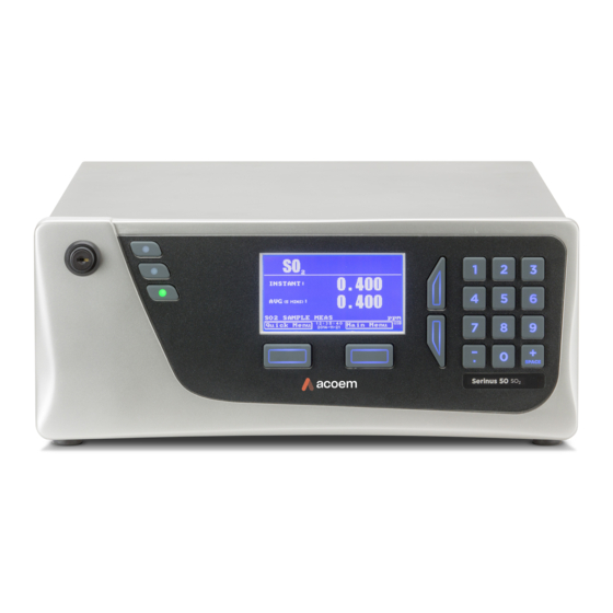
Serinus® 10 User Manual 3.2 3.3.2 Home Screen The home screen is composed of seven parts: readings (1), error/status line (2), instrument activity line (3), selection buttons (4), time/date (5), concentration units (6) and USB status (7). Figure 29 – Home Screen Readings (1) Displays the concentration being measured in real-time. - Page 53 should be inserted. Underneath the USB symbol arrows may be displayed which indicates data transfer. The USB memory stick must not be removed whilst the arrows are visible. Note: To safely remove the USB memory stick, navigate to the Quick Menu and use the Safely Remove USB Stick...
-
Page 54: Menus & Screens
Serinus® 10 User Manual 3.2 3.4 Menus & Screens Status Menu Temperature Menu Analyser State Menu Pressure & Flow Menu General Settings Menu Voltage Menu Measurement Settings Menu Pressure Calibration Menu Ozone Calibration Calibration Menu Menu Flow Calibration Menu Digital Pots Menu Internal Pump Menu Diagnostics Menu Service Menu... -
Page 55: Quick Menu
The menu system is divided into two sections selectable from the Home Screen: the Quick Menu Main Menu. The Quick Menu contains all information and operations necessary during scheduled maintenance visits. The Main Menu contains all fields that are accessible to users. It provides information on component failures and measurement parameters as well as editable fields and test procedures. -
Page 56: Main Menu
Serinus® 10 User Manual 3.2 Instrument Gain This is a multiplication factor which is used to adjust the concentration measurement to the appropriate level (set by performing a Span Calibrate O3). This should be recorded after each calibration in the station log book. Next Service Due A field that notifies the user when the next instrument service is due. -
Page 57: Analyser State Menu
Model This field will display the instrument model (e.g. Sernius 10). Nominal Range The measurement range of the instrument. Ecotech ID The Ecotech ID number. Serial No. The main controller PCA serial number. Board Revision The main controller PCA version. -
Page 58: Status Menu
Serinus® 10 User Manual 3.2 3.4.4 Status Menu Main Menu → Analyser State Menu → Status Menu Status Menu presents a list of the current Pass/Fail status of the main components. During warm-up, the status of some parameters will be a dashed line. Figure 33 –... -
Page 59: Temperature Menu
Diagnostic Control Error if the control loop is disabled (refer to Section 3.4.15). Valve Manual Control Error if the valves have been placed in manual control mode (refer to Section 3.4.18). O3 Gen. Manual Control Error if the Ozone generator is under manual control (refer to Section 3.4.12). -
Page 60: Pressure & Flow Menu
Serinus® 10 User Manual 3.2 Main Menu → Analyser State Menu → Temperature Menu The current temperature units of the instrument (Celsius, Temperature Units Fahrenheit or Kelvin). Set Point (LAMP) The temperature set point of the UV lamp. The factory default is 50 °C. -
Page 61: Voltage Menu
Sample Flow Indicates the gas flow through the sample port of the instrument. The value should be around 0.50 slpm. If there is an error with the sample flow, it will read 0.00 slpm. 3.4.7 Voltage Menu Figure 36 – Voltage Menu Screen Main Menu →... -
Page 62: General Settings Menu
Serinus® 10 User Manual 3.2 3.4.8 General Settings Menu Figure 37 – General Settings Menu Screen Main Menu → General Settings Menu Decimal Places Select the number of decimal places (0 - 5) used for the concentration displayed on the home screen. Conc. -
Page 63: Measurement Settings Menu
3.4.9 Measurement Settings Menu Figure 38 – Measurement Settings Menu Screen Main Menu → Measurement Settings Menu Average Period Set the time period over which the average will be calculated: Minutes (1, 2, 3, 4, 5, 6, 10, 12, 15, 20 or 30) or hours (1, 2, 4, 6, 8, 12 or 24) or rolling hourly averages over the last (4 or 8) hours. -
Page 64: Calibration Menu
Serinus® 10 User Manual 3.2 3.4.10 Calibration Menu Figure 39 – Calibration Menu Screen Main Menu → Calibration Menu Calibrating the instrument should be done with care (refer to Section 5 before using these menus). Cal. Type Depending on the selection in this field, a number of extra menu items will be displayed. - Page 65 Span Calibrate O3 This field is used to perform a span calibration and should be only used when a known concentration of span gas is running through the measurement cell and the reading is stable. Activating the span calibrate field for a named gas will open a dialog box.
-
Page 66: Pressure Calibration Menu
Serinus® 10 User Manual 3.2 Repeat The calibration will automatically run again after the specified amount of time. This field specifies the delay period (from 1 - 20,000 units, as specified below). Units This is where the user can define the type of units for the Repeat delay period. -
Page 67: Ozone Calibration Menu (Option)
Vacuum Cal Mode Defaults to Off. When turned On, the valves will be set to the same state as during a Vacuum Set Pt. adjustment, but there is no adjustment. Used for checking the accuracy of the vacuum pressure calibration. There are no dialog boxes or prompts, so the user needs to follow similar steps and precautions as during Vacuum Set Pt. -
Page 68: Flow Calibration Menu (Option)
Serinus® 10 User Manual 3.2 3.4.13 Flow Calibration Menu (Option) Figure 42 – Flow Calibration Menu Screen Main Menu → Calibration Menu → Flow Calibration Menu This menu only appears when the internal pump option is installed. Refer to Section 5.8 for the calibration procedure. -
Page 69: Service Menu
3.4.14 Service Menu Figure 43 – Service Menu Screen Main Menu → Service Menu Diagnostics Menu Refer to Section 3.4.15. Calculation Factors Menu Refer to Section 3.4.22. Load Auto-Backup Config. Loads the auto-backup configuration file. The configuration is automatically backed up every night at midnight. Load Configuration Loads a user selectable configuration file from the USB memory stick. -
Page 70: Diagnostics Menu
Serinus® 10 User Manual 3.2 3.4.15 Diagnostics Menu Figure 44 – Diagnostics Menu Screen Main Menu → Service Menu → Diagnostics Menu Digital Pots Menu Refer to Section 3.4.16. Internal Pump Menu Refer to Section 3.4.17. [Internal Pump Option] Valve Menu Refer to Section 3.4.18. - Page 71 Main Menu → Service Menu → Diagnostics Menu → Digital Pots Menu Digital pots are electronically controlled digital potentiometers used for adjustments to operations of the instrument. Each of the digital pots can go from 0 - 255. This menu should be accessed only during diagnostics.
-
Page 72: Internal Pump Menu (Option)
Serinus® 10 User Manual 3.2 Diagnostic Mode Operate Operate (default): Puts the instrument in normal operation Operate (default): Puts the instrument in normal operation mode. Electrical: Injects an artificial test signal into the electronic processing circuitry on the main controller PCA to verify that the circuitry is operating correctly. -
Page 73: Valve Menu
Pump Control Set to MANUAL to disable the automatic pump control. AUTO allows the flow PID to modify the pump coarse and fine settings. START will transition to AUTO after one second. Coarse Internal pump speed control (Coarse). This field is only editable when the Pump Control field is set to MANUAL. -
Page 74: Tests Menu
Serinus® 10 User Manual 3.2 Background/Measure Indicates if the Background/Measure valve on the Calibration Valve Manifold is Off or On. This will determine the port the instrument draws its sample from. Off = Flow from NO to C (drawing the sample through the O3 Scrubber into the Optical Cell). -
Page 75: Digital Input Test Menu
3.4.20 Digital Input Test Menu Figure 49 – Digital Input Test Menu Screen Main Menu → Service Menu → Diagnostics Menu → Tests Menu → Digital Input Test Menu Entering either the Digital Inputs Menu will temporarily disable all digital and analog input/outputs. This will affect logging via these outputs. -
Page 76: Calculation Factors Menu
Serinus® 10 User Manual 3.2 Output 0..7 Displays the state (On or Off) of the output pin and their corresponding pin out on the analog & digital I/O port (refer to Figure 73), and allows the user to manually set the state. Note: Entering either the Digital Outputs Menu will temporarily disable all digital and analog input/outputs. -
Page 77: Communications Menu
Undiluted O3 Displays the actual reading on the analyser before the dilution ratio is applied. If the Dilution ratio is 1 both undiluted O3 and diluted O3 field will be the same value. Dilution Ratio Entering a value here will multiply the displayed and recorded measurements by the dilution amount. -
Page 78: Data Logging Menu
Serinus® 10 User Manual 3.2 3.4.24 Data Logging Menu Figure 53 – Data Logging Menu Screen Main Menu → Communications Menu → Data Logging Menu When editing the numeric or text menus, the “-” key will delete the current parameter and move the others up to take its place;... -
Page 79: Analog Input Menu
14400, 19200, 38400 or 115200). Protocol Sets the protocol used for this serial port (Advanced, ModBus, EC9800 or Bayern-Hessen). This must be set to Advanced for Ecotech supplied software. Endian Select Little or Big endian mode for ModBus protocol. [Modbus Protocol] 3.4.26... -
Page 80: Analog Output Menu
Serinus® 10 User Manual 3.2 Input 1/2/3 The sections below are repeated for each analog input. Multiplier The input voltage will be multiplied by this number. For example, if a sensor has a 0 - 5 V output for a temperature of -40 °C to 60 °C, the multiplier would be (60 - (-40))/5 = 20. - Page 81 Over-Ranging Set to Enabled or Disabled to turn the over-ranging feature on or off. Over Range This field is only editable when Over-Ranging is set to Enabled. Set to the desired over range value. This value [Over-Ranging Enabled] cannot be set below the Range value. This is the alternate scale that is used for the analog output when over-ranging is active and enabled.
-
Page 82: Digital Input Menu
Serinus® 10 User Manual 3.2 3.4.28 Digital Input Menu Figure 57 – Digital Input Menu Screen Main Menu → Communications Menu → Digital Input Menu This menu is used to remotely trigger zero and span calibrations. This is done by assigning the eight digital inputs with one of the following commands. -
Page 83: Digital Output Menu
5. The same procedure can be followed to also activate zero calibrations. Pin 6 of the instrument’s analog/digital 25 pin female connector can be connected to one of the other master devices digital outputs and the instrument can be set so DI 1 is assigned to Zero. -
Page 84: Network Menu (Option)
Serinus® 10 User Manual 3.2 Digital Output State Description Background Performing a background. Span Performing a span check. Zero Performing a zero check. System Fault Any system fault (the red light is ON). Maintenance Mode User has activated maintenance mode. Over Range A0 1 Over range for the analog output when channel 0 is active. -
Page 85: Bluetooth Menu
[DHCP mode] Protocol Sets the protocol used for the network port (Advanced, ModBus, EC9800 or Bayern-Hessen). This must be set to Advanced for Ecotech supplied software. Endian Select Little or Big endian mode for ModBus protocol. [Protocol Modbus] Bayern-Hessen Serial ID This is the Bayern-Hessen ID used by the Bayern-Hessen Protocol. -
Page 86: Trend Display Menu
The default ID setting is Serinus (Ecotech ID). The word Serinus is always the first part of the name and cannot be edited. The second part is the Ecotech ID. 3.4.32 Trend Display Menu Figure 61 –... -
Page 87: Chart
3.4.33 Chart Main Menu → Trend Display Menu → Chart The chart allows the user to select a parameter and view it in a real time chart. The user can select from any loggable parameter (refer to Table 25). Changing the logged parameter will reset the chart. Pressing the Up or Down buttons will change between the selected parameter and the instantaneous Ozone gas value. -
Page 88: Table 7 - Chart Navigation Buttons
Serinus® 10 User Manual 3.2 Data Points (9) Displays the last 240 data points recorded for the selected parameter. Chart Cursor (10) If the user wishes to know the value at any at a particular data point on the chart, the cursor can be used. -
Page 89: Advanced Menu
3.4.34 Advanced Menu This menu is accessed via a different method than the other menus. From the Home Screen press the ( . ̅)99( following keys: SPACE This menu contains technical settings, diagnostics and factory hardware installations. No items in this menu should be accessed without authorisation and supervision of qualified service personnel. -
Page 90: Hardware Menu
Serinus® 10 User Manual 3.2 3.4.35 Hardware Menu Advanced Menu → Hardware Menu Figure 64 – Hardware Menu Screen This menu contains factory hardware installations. If the user reset to factory defaults then they may need to revisit this menu to enable your installed optional features. Model Select the instrument model. -
Page 91: Parameter Display Menu
3.4.36 Parameter Display Menu Advanced Menu → Parameter Display Menu Figure 65 – Parameter Display Menu Screen Used to display a parameter in real-time on the screen (refer to Table 25 for a full list of parameters). Data Parameter This is an editable field. Enter the parameter number you wish to view (refer to Table 25). - Page 92 Serinus® 10 User Manual 3.2 This page is intentionally blank. Page 92...
-
Page 93: Communications
USB, 25 pin digital/analog input/output, TCP/IP network (optional) and Bluetooth). A demonstration version of Ecotech’s Airodis software is included with the instrument, enabling basic data downloads and remote operation from a PC running a supported MS Windows operating system. The full version of Airodis is available separately and includes automated collection, data validation and complex reporting by multiple users. -
Page 94: Usb Communication
Figure 67 – Multidrop RS232 Cable Example 4.2 USB Communication This is ideal for irregular connection to a laptop running Ecotech’s Airodis software to download logged data and remotely control the instrument. Due to the nature of USB, this is a less reliable permanent connection as external electrical noise can cause USB disconnection errors on a data logger. -
Page 95: Tcp/Ip Network Communication (Optional)
4.3 TCP/IP Network Communication (Optional) Instruments with the optional network port installed can be accessed using a TCP/IP connection. Figure 68 shows examples of some possible configurations for remote access. Figure 68 – Example of Typical Network Setups Communications Page 95... -
Page 96: Reading Network Port Setup
Serinus® 10 User Manual 3.2 Note: In Figure 68 all the IP addresses are taken as an example. The WAN IP addresses are normally provided by your ISP. Whereas, the LAN IP addresses can be set manually to any range which is within the subnet of the Modem/Router/switch. -
Page 97: Port Forwarding On Remote Modem/Router Setup
6. Select - Protocol → Advanced - Accept. Figure 69 – Example of Network Menu Setup 7. Once completed, use the power switch on the rear of the instrument to turn the power OFF. Leave the instrument OFF for 10 seconds before turning the power back ON. Note: Manually perform a hardware power cycle every time the IP address is changed for it to take effect. -
Page 98: Airodis Setup To Communicate With Serinus
Serinus® 10 User Manual 3.2 4.3.4 Airodis Setup to Communicate with Serinus Below is an example of Airodis setup for a LAN network. Ensure the IP address is set to the same as on the instrument Network Menu. Figure 71 – LAN Network Set-Up (Airodis) Below is an example of Airodis setup for a WAN network. -
Page 99: Analog And Digital Communication
4.4 Analog and Digital Communication The 25 Pin analog and digital I/O port on the rear panel of the instrument sends and receives analog and digital signals to other devices. These signals are commonly used to activate gas calibrators or for warning alarms. -
Page 100: Analog Inputs
Serinus® 10 User Manual 3.2 4.4.2 Analog Inputs The instrument is also equipped with three analog inputs with resolution of 15 bits plus polarity, accepting a voltage between 0 - 5 V. These go directly to the microprocessor and should be protected to ensure static/high voltage does damage the main controller PCA (instrument warranty does not cover damage from external inputs). -
Page 101: Logging Data
Figure 74 – Analog & Digital I/O Individual Pin Descriptions CAUTION The analog and digital inputs and outputs are rated to CAT I. Exceeding 12 VDC or drawing greater than 400 mA on a single output or a total greater than 2 A across the eight outputs can permanently damage the instrument and void the warranty. -
Page 102: Using Airodis Software To Download Data
Serinus® 10 User Manual 3.2 4. Edit - (Change one of the storage locations “Parameter 1 - 12” to the parameter number user wish to log) - Accept 4.5.1.2 Data Log –Text Procedure 1. Open - Main Menu → Communications Menu → Data Logging Menu (refer to Section 3.4.23). 2. -
Page 103: Figure 76 - Update Driver Popup
When prompted where to search for the driver, select “Browse my computer for driver software”. Figure 76 – Update Driver Popup The Serinus USB driver is located on the green Ecotech resources USB stick under “\Drivers\Ecotech Analyser”. Select this directory and click Next. -
Page 104: Figure 78 - Installing Driver Confirmation Prompt
Serinus® 10 User Manual 3.2 If the user receives a confirmation prompt to install the driver, select Install. Figure 78 – Installing Driver Confirmation Prompt If everything went smoothly, Windows will inform the user that the driver was successfully installed. Figure 79 –... -
Page 105: Installing Airodis
The user can download data from the instrument using either a full retail (paid) version of Airodis or with the demo version which is included on the green Ecotech resources USB stick. The demo version has limited functionality, but will allow the user to download and export data from up to three instruments. -
Page 106: Figure 81 - Adding A New Station
Logger Set this to “Ecotech Serinus” when downloading from any Serinus series instrument. This will communicate with the instrument via the Advanced protocol. If using a network or serial connection, ensure that the Advanced protocol has also been selected on the instrument itself. -
Page 107: Figure 83 - Station Configuration (Channel List)
Property Description Device ID Enter the Serial ID of the instrument. If the user is not using multidrop; this can be set to “0” or left blank. Link Type Select the type of connection used to connect to the instrument. Different properties will appear depending on the link type selected. -
Page 108: Figure 85 - Downloading Data
Serinus® 10 User Manual 3.2 7. Select the Data Manager tab, click download. The Download Data window will appear. Select the appropriate time period that the user wishes to download and click Download. Figure 85 – Downloading Data 8. The status of the download will appear in the bottom-left corner of the window. The user can also monitor the status of the download from the Home tab. -
Page 109: Figure 87 - Data Visibility
9. Data will become available in the data manager as it is downloaded. The user can load data for a date range by entering the start and end dates and clicking Display. The selected data will be loaded into the data manager. Figure 87 –... -
Page 110: Serinus Remote App/Bluetooth
Serinus® 10 User Manual 3.2 11. That’s it! The data has been downloaded from the instrument and exported to a standard CSV file. Figure 89 – Data Download Complete 4.7 Serinus Remote App/Bluetooth The Serinus Remote Application allows for any Android device (Tablet or Smartphone) to connect to an instrument. -
Page 111: Installation
4.7.1 Installation The Serinus Remote Application can be found in the Google Play Store by searching for Ecotech or Serinus. Once found, choose to Install the application and Open to start the application. Figure 90 – Downloading the App from Google Play Store Note: A menu containing additional features and functions can be accessed by entering the Options Menu (or similar) on your device. -
Page 112: Instrument Control
Serinus® 10 User Manual 3.2 9. A screenshot of the instrument’s current screen should appear on the user smartphone or tablet. To disconnect press the back key/button on the device. Note: Once the instrument has been paired with the device it will appear under “Paired Devices” and the PIN will not need to be entered again. -
Page 113: Figure 93 - Switching Instruments
Left-hand Section of the Screen Swiping from left to right brings up a list of available instruments (swipe from right to left to hide the instrument list). Figure 93 – Switching Instruments Back Button This button will enable the user to return to the selection screen, allowing connection to a different instrument. -
Page 114: Real-Time Plot
Serinus® 10 User Manual 3.2 4.7.4 Real-Time Plot Allows the user to view real-time plotting of up to four parameters at the same time. The user can also scroll from left to right, top to bottom or zoom in and out on the plot by swiping/pinching. Once the plot is zoomed or scrolled, it enters into Observer Mode, meaning that auto-scaling is suspended. -
Page 115: Download
4.7.5 Download Download logged data from the USB memory stick inside the instrument. All data logged by the instrument to the USB memory stick over the period of time specified will be collected. Due to the slow connection speed of Bluetooth, this should only be used for relatively short sections of data. Downloading one days’... -
Page 116: Preferences
Serinus® 10 User Manual 3.2 Options Menu Get Parameters Refreshes the parameter list display. Save Generates a filename from the current date and time, saves the parameter data in the location specified in preferences and asks to send the saved text file as an attachment to an email. -
Page 117: Figure 98 - Colour Theme Settings
Colour Theme Settings Colour theme settings, allows the user to choose a colour scheme for the remote screen: Matrix, Classic, Emacs or Custom. Figure 98 – Colour Theme Settings Communications Page 117... - Page 118 Serinus® 10 User Manual 3.2 This page is intentionally blank. Page 118...
-
Page 119: Calibration
5. Calibration The following sections describe how to calibrate the zero and span points of the instrument as well as giving a brief overview of the calibration system. Main Menu → Calibration Menu (refer to Section 3.4.10 for information on menu items). 5.1 Overview Figure 99 –... -
Page 120: Using Transfer Standards - Overview
Note: Zero calibrations are not recommended by Ecotech, but maybe be performed when specifically required by a user. Zero calibrations tend to mask issues that should be addressed during maintenance/service. -
Page 121: Principle
5.2.1 Principle In ambient air monitoring applications, precise Ozone concentrations called standards are required for the calibration of Ozone analysers. Due to the instability of Ozone, concentrations must be generated and “verified” on site with another instrument referred to as a transfer standard. A transfer standard is defined as a transportable device or apparatus which is capable of accurately reproducing Ozone. -
Page 122: Set-Up
Ozone Transfer Standard Level 3 and greater – At beginning and end of Ozone season or every 6 months whichever is less. Ecotech is able to offer a Level 2 and lower Ozone calibration service. Note: Transfer standards must meet the requirements and specifications set forth by the user’s local regulatory authority. -
Page 123: Pressure Calibration
Consideration should be given to locating the calibration photometer in a clean laboratory where it can be stationary, protected from physical shock, operated by a responsible analyst and used as a common standard for all field calibrations via transfer standards. Note: It is the user’s responsibility to verify the appropriate transfer standard is chosen and maintained in accordance with local standards. -
Page 124: Figure 102 - Full Pressure Calibration Set-Up (Vacuum)
Serinus® 10 User Manual 3.2 6. Connect a vacuum source to Exhaust Port of the instrument. Figure 102 – Full Pressure Calibration Set-up (Vacuum) 7. Wait 2 - 5 minutes and ensure the pressure reading on the barometer has dropped and is stable. 8. -
Page 125: Pressure Calibration (Ambient Only)
5.3.2 Pressure Calibration (Ambient Only) Full pressure calibrations are generally recommended, however it is possible to calibrate only the ambient point in cases where only a minor ambient pressure adjustment is required. Note: Ensure that the instrument has been running for at least one hour before any calibration is performed to ensure the instrument’s stability. -
Page 126: Pressure Calibration (Internal Pump Option Only)
Serinus® 10 User Manual 3.2 5.3.3 Pressure Calibration (Internal Pump Option Only) The internal pump requires a separate pressure calibration procedure that replaces the one used in Section 5.3.1 and 5.3.2. Note: Ensure that the instrument has been running for at least one hour before any calibration is performed to ensure sufficient stability. -
Page 127: Zero Calibration
A large offset may indicate a problem with the instrument (refer to Section 7). Note: Ecotech encourages regular zero precision checks; however Ecotech recommends that the zero calibration only be performed when specifically required as it may mask issues that should be addressed during maintenance/service. -
Page 128: Calibration Port
Serinus® 10 User Manual 3.2 Note: Ensure the instrument has been running for at least one hour before any calibration is performed to ensure sufficient stability. 5.4.1 Calibration Port Equipment Required • Zero Air Source (refer to Section 1.3 for definition) Procedure 1. -
Page 129: Izs (Option)
Procedure 1. Ensure a suitable zero air source is connected to the Sample Port. Figure 108 – Zero Calibration Set-up - 2 2. Open - Main Menu → Calibration Menu. 3. Select - Cal. Type → Manual - Accept. 4. Select - Cal. Mode → Measure - Accept. 5. -
Page 130: Span Calibration
5.5 Span Calibration A span calibration is a calibration performed at the upper end of the instrument’s measurement range. Ecotech recommends calibration at 80% of the full scale measurement or operating range of the instrument. While the instrument range is commonly set as a default 0 - 500 ppb, this is widely recognised as no longer being valid with modern digital communication and most regulators will now recommend a range more suited to local conditions. -
Page 131: Precision Check
Procedure 1. Ensure suitable span source is connected to the Sample Port. 2. Set the span source output concentration to 80% of the instrument measurement range. 3. Open - Main Menu → Calibration Menu. 4. Select - Cal. Type → Manual - Accept. 5. -
Page 132: Span Precision Check
Serinus® 10 User Manual 3.2 5.6.2 Span Precision Check Equipment Required • Span source Procedure 1. Supply the instrument with a span source (refer to Section 5.5 for the procedure of setting up a span but do not do a Span Calibrate O3, and continue following below steps) (If using internal IZS refer to Section 5.6.2.1). -
Page 133: Multipoint Precision Check
Response). Ensure that the instrument has been running for at least one hour before any calibration is performed to ensure sufficient stability. 1. Ensure a suitable span source is connected to the instrument from a gas calibrator (Ecotech recommends the Serinus Cal 3000) through the Calibration Port (refer to Section 5.5.1). -
Page 134: Flow Calibration (Internal Pump Option Only)
Serinus® 10 User Manual 3.2 4. The linear regression equation will be displayed. �� = ���� + �� Figure 109 – Excel Graph of Multipoint Calibration 5. The following is a guide to approximate expected good results. a. The gradient (m) falls between 0.98 and 1.02. b. -
Page 135: High Pressure Zero Valve (Option)
Procedure 1. Disconnect any external tubing connected to the rear ports of the instrument (Sample Port, Exhaust Port, etc.). 2. Open - Main Menu → Calibration Menu → Flow Calibration Menu. → 3. Select - Pump Control MANUAL - Accept. 4. -
Page 136: Single Pressurised Calibration (Option)
Serinus® 10 User Manual 3.2 5.9.1 Single Pressurised Calibration (Option) Set-Up of Single Calibration Option Figure 110 – Single High Pressure Calibration Option When using the pressurised calibration option a high pressure zero should be connected to the Calibration Port. Equipment Required •... - Page 137 5. Temporarily place a flow meter on the Vent Port. 6. Open - Main Menu → Calibration Menu. 7. Select - Cal. Type → Manual - Accept. 8. Select - Cal. Mode → Zero - Accept Note: When using the high pressure zero option, ensure Zero Source is set to External. 9.
- Page 138 Serinus® 10 User Manual 3.2 This page is intentionally blank. Page 138...
-
Page 139: Service
6. Service 6.1 Additional Safety Requirements for Service Personnel In addition to Safety Information stated previously, service personnel are also advised of the following: • Documentation must be consulted in all cases where caution symbol is marked, in order to find out the nature of the potential hazards and any actions which have to be taken to avoid them. -
Page 140: Maintenance Schedule
6.3 Maintenance Schedule The maintenance intervals are determined by compliance standards that differ in various regions. The following is recommended by Ecotech as a guide. Compliance with local regulatory or international standards is the responsibility of the user. Page 140... -
Page 141: Table 9 - Maintenance Schedule
Table 9 – Maintenance Schedule Interval * Task Performed Section Nightly Perform precision check (Automated) Every 5 days Perform precision check (Manual) (This task is performed to ensure a high data capture rate) Perform precision check (pre-check) prior to commencing any Monthly service tasks or making any changes to the system as found in its current state. -
Page 142: Maintenance Procedures
Serinus® 10 User Manual 3.2 6.4 Maintenance Procedures 6.4.1 Particulate Filter Replacement Contamination of the 5 micron filter can result in degraded performance of the instrument, including slow response time, erroneous readings, temperature drift and various other problems. The frequency which the filter needs to be replaced is heavily dependent on the environmental conditions the instrument is sampling. -
Page 143: Figure 117 - Remove Filter Sealing Cap
5. Remove the sample filter holder sealing cap. Figure 117 – Remove Filter Sealing Cap 6. Remove the old particulate filter. Figure 118 – Particulate Filter 7. If the inner surface of the sample filter components are dirty, then clean with damp lint free paper towel. -
Page 144: Clean Chassis Fan Filter
Serinus® 10 User Manual 3.2 Figure 119 – Avoid to Touch Particulate Filter Paper 9. Replace the sample filter holder sealing cap and re-assembly the retaining ring by turning it clockwise. Note: Make sure O-ring and particulate filter paper are installed correctly Note: Make sure that Kynar Elbow Barb Fitting is in the right direction, refer to Figure 120. -
Page 145: Leak Check
1. Remove outer filter casing and filter (refer to Figure 121). Figure 121 – Remove Filter Casing and Filter 2. Clean filter with water and dry it. Note: Do not install the filter until completely dry, a wet filter can damage the instrument. 3. -
Page 146: Figure 123 - Connect Vacuum Source
Serinus® 10 User Manual 3.2 Connect a vacuum source to the shut off valve ensuring the shut off valve is in the open position. Figure 123 – Connect Vacuum Source 5. Open - Main Menu → Service Menu → Diagnostics Menu → Valve Menu. →... -
Page 147: Figure 125 - Pressure Gauge On Leak Test Jig
13. If the instrument did not leak, skip to step 16. Figure 125 – Pressure Gauge on Leak Test Jig 14. Inspect the instrument’s plumbing looking for obvious damage. Check the condition of fittings, sample filter holder plus the O-rings. 15. -
Page 148: Figure 126 - Pump Bypass Flow
Serinus® 10 User Manual 3.2 6.4.3.1 Leak Check (Internal pump option) Equipment Required • Barometer • Kynar 1/4” Blocker Nuts • 5/8” Spanner Procedure Note: Ensure that the instrument has been running for at least one hour before this procedure is performed. -
Page 149: Figure 127 - Barometer To Sample Port
12. Connect the barometer to Sample Port. Figure 127 – Barometer to Sample Port 13. Allow the internal pump time to evacuate the pneumatic system (the time required will depend on the condition of the pump, 1 - 2 minutes). 14. -
Page 150: Ozone Scrubber Check
Serinus® 10 User Manual 3.2 22. Connect the barometer to Calibration Port. Figure 128 – Barometer to Calibration Port 23. Allow the internal pump time to evacuate the pneumatic system (the time required will depend on the condition of the pump, 1 - 2 minutes). 24. -
Page 151: Figure 129 - Connect Span Source
If a faulty Ozone scrubber is suspected perform the following steps: Equipment Required • Reference Ozone Scrubber • Span Source of 400 ppb Ozone Procedure 1. Connect a span source (approximately 0.400 ppm O ) to the sample port, allow the instrument to stabilise. -
Page 152: Clean Pneumatics
Serinus® 10 User Manual 3.2 2. Remove the Kynar ¼”nut located on the elbow at the top of the scrubber to be changed. Disconnect the elbow. Figure 131 – Remove the Kynar Nut 3. Release the scrubber from the retaining clip. 4. -
Page 153: Figure 132 - Loosening Tube Collet From Detector End
Procedure Obey below procedure to clean the optical cell: 1. Turn OFF the Vacuum source and allow the instrument to return to ambient. 2. Turn OFF the instrument. 3. Open the lid of the instrument to access the Optical Bench (refer to Section 2.1, Opening the Instrument). -
Page 154: Figure 134 - Removing Detector Block From Optical Cell
Serinus® 10 User Manual 3.2 6. Slowly move side to side and pull the detector block away from the tube removing it completely. CAUTION Be careful while installing or removing the tube, as it may fracture and cause serious injury to the user. Figure 134 –... -
Page 155: Figure 136 - Removing Measurement Cell (Glass)
8. Pull the tube cover back away from the lamp block and carefully remove the measurement cell (glass) slowly moving side to side and pulling out. Figure 136 – Removing Measurement Cell (Glass) 9. Inspect the tube for any particulate matter deposited on the inner walls of the measurement cell (glass). -
Page 156: Uv Lamp Check
Serinus® 10 User Manual 3.2 6.4.7 UV Lamp Check The UV lamp intensity decreases over time, to compensate for this the instrument will increase the Input pot. When the Input Pot increases above 200 the lamps intensity is not suitable for accurate measurement and the UV lamp should be replaced. -
Page 157: Orifice/Sintered Filter Replacement
6.4.8 Orifice/Sintered Filter Replacement In the situation where the instrument’s orifice or sintered filter need to be inspected or replaced the following procedure should be followed. Equipment Required • Orifice/Sintered Filter Extraction Tool (H010046) • Spanner 5/8” • Teflon Tape Procedure 1. -
Page 158: Figure 140 - Remove Lamp Mounting Block
Serinus® 10 User Manual 3.2 6. Now that we have isolated the lamp block, remove the screw to dismantle the lamp mounting block. Note: Be careful while dismantling lamp mounting block Quartz Window may fall on the ground. Figure 140 – Remove Lamp Mounting Block 7. -
Page 159: Pressure Sensor Check
10. Remove the remaining o-ring and sintered filter. Figure 142 – Remove Orifice and Sintered Filter 11. Replace the sintered filter and o-ring. If you were getting the incorrect flow check the orifice isolated from the instrument. If flow of the isolated orifice is still bad clean or replace orifice. Ideally the orifice should be cleaned in a sonic bath with lab detergent and water. -
Page 160: Bootloader
To enter the Bootloader turn OFF the power to the instrument. Press and hold the plus key while turning the power on. Hold the Plus key until the following screen appears. ** Ecotech Serinus Analyser ** V3.1 Bootloader Press ‘1’ to enter Bootloader If the instrument displays the normal start up screen, the power will need to be toggled and another attempt will need to be made to enter the Bootloader. -
Page 161: Display Help Screen
2 key from the Bootloader screen. 6.5.3 Updating Firmware It is important for optimal performance of the instrument that the latest firmware is loaded. The latest firmware can be obtained by visiting Ecotech’s website: http://www.ecotech.com/downloads/firmware Or by emailing Ecotech at service@ecotech.com support@ecotech.com... - Page 162 Serinus® 10 User Manual 3.2 This page is intentionally blank. Page 162...
-
Page 163: Troubleshooting
7. Troubleshooting Before troubleshooting any specific issues, Ecotech recommends ensuring the instrument has successfully completed its start-up routine and all issues listed in the instrument status menu are resolved (refer to Section 3.4.4). Table 10 – Troubleshooting List Error Message/Problem... - Page 164 Serinus® 10 User Manual 3.2 UV Lamp Temp Failure Faulty heater or Refer to Section 7.3. temperature sensor Analyser Resetting Multiple possibilities Check that the instrument is not overheating. Possibly a faulty power supply. Electrical issue component shorted to ground. Corrupted firmware, perform a ‘erase all settings’...
- Page 165 Low Span Leaks A leak in the instrument or calibration system dilutes the sample stream and causes low span Selective scrubber readings and noise. Preform Ozone scrubber check (refer to Section 6.4.4). Span calibration out Adjust the span using the calibration procedure (refer to Section 5.5).
-
Page 166: Flow Fault
Serinus® 10 User Manual 3.2 7.1 Flow Fault Figure 144 – Flow Fault Diagnostic Procedure ** Section 2.3.2 *** Section 5.3 Page 166... -
Page 167: Noisy/Unstable Readings
7.2 Noisy/Unstable Readings Figure 145 – Noisy Zero or Unstable Span Diagnostic Procedure ** Section 6.4.3 *** Section 5.3 Troubleshooting Page 167... -
Page 168: Lamp Temperature Failure
Serinus® 10 User Manual 3.2 7.3 Lamp Temperature Failure Figure 146 – Lamp Temperature Failure Diagnostic Procedure Page 168... -
Page 169: Usb Memory Stick Failure
7.4 USB Memory Stick Failure Figure 147 – USB Memory Stick Failure Troubleshooting Page 169... -
Page 170: Ecotech Service Support Files
7.5 Ecotech Service Support Files Regular backup of the settings, parameters and data on the instruments USB memory stick is recommended. In the event of a fault that requires Ecotech technical support, make copies of the following files and email to: support@ecotech.com Equipment Required •... -
Page 171: Figure 148 - Usb Memory Stick File Structure
Figure 148 – USB Memory Stick File Structure 10. Insert the USB memory stick into PC/Laptop computer and access the files. 11. Best practice is to email all the on the USB memory stick but if it’s to large just send: 12. - Page 172 Serinus® 10 User Manual 3.2 This page is intentionally blank. Page 172...
-
Page 173: Optional Extras
8. Optional Extras This section contains information on optional kits and installed options: Dual Sample Filter Refer to Section 8.1. Network Port Refer to Section 8.2. Rack Mount Kit Refer to Section 8.3. Internal Pump Refer to Section 8.4. Pressure Zero Valve Refer to Section 8.5. -
Page 174: Hardware Setup
Serinus® 10 User Manual 3.2 8.2.1 Hardware Setup This procedure will need to be followed after a factory reset. Procedure 1. Press - (the green instrument status light button), this will take user to the home screen. 2. Press - (-99+) on the keypad. This will open the Advanced Menu. 3. -
Page 175: Figure 151 - Assemble Inner Slide On Chassis
3. Attach the inner slide rails to each side of the instrument using M4 x 10 button screws; three on each side (refer to Figure 151). Figure 151 – Assemble Inner Slide on Chassis 4. Install rack mount ears on the front of the instrument using two M4 x 10 screws on each side (refer to Figure 152). -
Page 176: Figure 153 - Attach Rack Mount Adaptors To Outer Slides
Serinus® 10 User Manual 3.2 5. Attach the rack mount adaptors to the ends of the outer slide rails using M4 x 10 button screws, washers and locknuts. Do not fully tighten at this stage as minor adjustments will be required to suit the length of the rack (refer to Figure 153). -
Page 177: Figure 155 - Attach Slides To Front Of Rack
7. Install the two assembled outer slide rails onto the left and right side of the rack securely with M6 bolts; washer and locknuts/cage nuts (refer to Figure 155). Figure 155 – Attach Slides to Front of Rack 8. Now carefully insert the instrument into the rack by fitting the instrument slides into the mounted rails. -
Page 178: Internal Pump (Pn: E020105)
Serinus® 10 User Manual 3.2 8.4 Internal Pump (PN: E020105) Note: Serinus 10 with both IZS and Internal Pump options is currently under development. Contact Ecotech for more information. 8.4.1 Hardware Setup This procedure should be followed after a factory reset. -
Page 179: Internal Pump Removed Components
8.4.3 Internal Pump Removed Components The Serinus 10 has a number of components missing from the standard instrument due to the presence of the internal pump and flow block controlling flow within the instrument. The parts that have been removed when this option is installed are listed in the table below: Table 13 –... -
Page 180: High Pressurised Zero Valve (Pn: E020109)
(e.g. Level 2 calibration). Note: Serinus 10 with both IZS and Internal Pump options is currently under development. Contact Ecotech for more information. The Serinus 10 can be fitted with an internal Ozone generator and Ozone scrubber to provide span gas and zero air for calibration. -
Page 181: Izs Removed Components
Component Part number Heater and Thermistor Cable C020125 Figure 157 – IZS Additional Components 8.6.3 IZS Removed Components The Serinus 10 has a number of components missing from the standard instrument due to the presence of the IZS within the instrument. The parts that have been removed when the IZS option is included are: Table 15 –... -
Page 182: Serinus 10 Schematic With Izs Option
Serinus® 10 User Manual 3.2 8.6.4 Serinus 10 Schematic with IZS Option Figure 158 – IZS Schematic 8.6.5 Ozone Generator Characterisation This procedure allows the instrument to characterise the Ozone generation of the lamp to provide accurate internal span points. This should be done whenever the lamp is adjusted, changed or when the generated output of Ozone no longer matches the set point. -
Page 183: Parts List And Schematics
9. Parts List and Schematics 9.1 Serinus Accessories Kit This kit contains assorted fittings, tubing and an orifice removal tool which are useful when working on the instruments internal pneumatics. This is usually purchased with the instrument. Table 16 – Serinus Accessories Kit H010136 Serinus Accessories Kit: Part Numbers Quantity... -
Page 184: Consumables
Serinus® 10 User Manual 3.2 Serinus 10 Maintenance Kit: E020201 Part Number Quantity O-ring 13/16ID X 1/16W, VITON O010016 O-ring BS015, VITON O010023 O-ring .364ID X .07W, Silicone O010024 O-ring .359ID X .139W, Silicone O010025 O-ring, 1.989ID x 0.07W, BS033, VITON O010054 Tubing, K FLEX, 1/4 X 1/8 T010026... -
Page 185: Instrument Parts List
9.4 Instrument Parts List List of Serinus 10 components and part numbers for reference: Table 19 – Spare Parts List (Main Components) Part Description Part Number Main Controller PCA C010014 Calibration Valve Manifold H010013-02 Rear Panel PCA C010002-01 Front Panel Assembly H010130 Sample Filter Holder H010160... -
Page 186: Table 21 - Spare Parts List (O-Rings)
Serinus® 10 User Manual 3.2 Part Description Part Number Detector PCA Cable C020080 Heater and Thermistor Cable C020081 Bluetooth Cable C020119 Table 21 – Spare Parts List (O-rings) Part Description Part Number O-ring, 1/4 ID X 1/16 W O010015 O-ring, 1.989 ID x 0.07 W O010054 O-ring, 1/2 ID X 3/32 W O010005... -
Page 187: Table 24 - Spare Parts List (Shipping)
Part Description Part Number Sample Filter mounting Plate H010126 Roller Bearing H010131 Power Supply Bracket H010138 Rear Panel H010142 Push Button Slam Lock H030114 Nylon P Clip, 1/2" (12.7Mm) H030149 #40 Scrubber Support Ring H010114 Circuit Board Support Bracket H010117 Serinus 10 O3 Label H010132-01 M3 X 6 Standoff, Male-Female... -
Page 188: Plumbing Schematic - (Pn: D020004)
Serinus® 10 User Manual 3.2 9.5 Plumbing Schematic – (PN: D020004) Page 188... -
Page 189: Plumbing Schematic - (Pn: D020050)
9.6 Plumbing Schematic – (PN: D020050) Parts List and Schematics Page 189... -
Page 190: Plumbing Schematic - (Pn: D020051)
Serinus® 10 User Manual 3.2 9.7 Plumbing Schematic – (PN: D020051) Page 190... -
Page 191: Block Wiring Schematic - (Pn: D020101)
9.8 Block Wiring Schematic – (PN: D020101) Parts List and Schematics Page 191... -
Page 192: Block Wiring Schematic - (Pn: D020121)
Serinus® 10 User Manual 3.2 9.9 Block Wiring Schematic – (PN: D020121) Page 192... -
Page 193: Optical Bench/Photometer Assembly - (Pn: H013100)
9.10 Optical Bench/Photometer Assembly – (PN: H013100) Parts List and Schematics Page 193... -
Page 194: Calibration Manifold Assembly - (Pn: H010013-02)
Serinus® 10 User Manual 3.2 9.11 Calibration Manifold Assembly – (PN: H010013-02) Page 194... -
Page 195: Valve Assembly - (Pn: H010042)
9.12 Valve Assembly – (PN: H010042) Parts List and Schematics Page 195... -
Page 196: Charcoal Scrubber Assembly - (Pn: H010038)
Serinus® 10 User Manual 3.2 9.13 Charcoal Scrubber Assembly – (PN: H010038) Page 196... -
Page 197: Calibration Manifold Assembly (Izs) - (Pn: H010056)
9.14 Calibration Manifold Assembly (IZS) – (PN: H010056) Parts List and Schematics Page 197... -
Page 198: Sample Filter Holder Assembly - (Pn: H010160)
Serinus® 10 User Manual 3.2 9.15 Sample Filter Holder Assembly – (PN: H010160) Page 198... -
Page 199: Ozone Generator Assembly - (Pn: H013150)
9.16 Ozone Generator Assembly – (PN: H013150) Parts List and Schematics Page 199... - Page 200 Serinus® 10 User Manual 3.2 This page is intentionally blank. Page 200...
-
Page 201: Table 25 - Advanced Protocol Parameter List
Appendix A. Advanced Protocol Parameter List Note: Parameters are for all Serinus series analysers and may not be applicable to an individual instrument. Table 25 – Advanced Protocol Parameter List Description Notes Cal/Zero Valve 0 = Zero, 1 = Cal Internal Span Valve 0 = OFF, 1 = ON +Analog Supply... - Page 202 Serinus® 10 User Manual 3.2 Analog input 5 Cell pressure Analog input 6 Ambient pressure Analog input 7 Raw ADC calibration input Analog input 8 Reserved Analog input 9 Concentration data Analog input 10 Reserved Analog input 11 Reserved Analog input 12 Raw analog to digital count for external analog input 0.
- Page 203 Decimal Places 2 - 5 Noise Instrument noise Gas 1 Offset An offset applied to Gas 1 Gas 3 Offset An offset applied to Gas 3 Flow Temperature Temperature of the flow block Lamp Current Lamp current in mA E.g 35mA +5V Supply Digital Supply voltage (should always read close to 5 volts) Conc.
- Page 204 Serinus® 10 User Manual 3.2 Instrument Out of Service (or in Diagnostic mode, PTF compensation or control loop disabled, or Comms debugging enabled) High Voltage failure System power failure (not actually possible to report) Reference voltage failure Cell temperature failure Cooler failure Converter failure Correlation wheel failure...
- Page 205 Output Type AO 0 Output Type 1 = Voltage Output Type AO 1 0 = Current Output Type AO 2 Anlg Ofst/Rng AO 0 Voltage Offset /Current Range 0 = 0% or 0 - 20mA Anlg Ofst/Rng AO 1 1 = 5% or 2 - 20mA Anlg Ofst/Rng AO 2 2 = 10% or 4 - 20mA F/Scale Volt AO 0...
- Page 206 Serinus® 10 User Manual 3.2 24 = Span Measure Aux2 25 = Background Fill Span 26 = Background Measure Span 27 = Background Purge Span 28 = Electronic Zero Adjust 29 = Instrument Warm Up 30 = Background Adjust Fill 31 = Background Adjust Measure CO Lin.
- Page 207 Perm Flow Total flow past the permeation chamber during an activated internal span mode. In ml/min Perm Oven Setpoint Set target temperature for the permeation oven. Default is 50°C Perm Oven Temp Temperature readout of the Permeation oven. Units in °C Ozone Target Ozone Target for S10 IZS Ozone generation Conc Adjusted 1...
- Page 208 Serinus® 10 User Manual 3.2 Valve States Diagnostic use only Temperature Units 0 = "°C" 1 = "°F" 2 = "K" Pressure Units 0 = "torr" 1 = "psi" 2 = "mbar" 3 = "atm" 4 = "kPa" Averaging Period 0 = "1 Min"...
- Page 209 3 = 6 Hrs 4 = 4 Hrs 5 = 2 Hrs 6 = Disable Note: this parameter is deprecated; while it can still be read, writing to it will have no effect. Use parameter 144 instead. Service (COM1) Baud Serial baud rate 0 = 1200 bps Multidrop (COM2) Baud...
- Page 210 Serinus® 10 User Manual 3.2 Gas 5 Inst. Calculated gas concentration currently displayed on front screen E.g. Nx NH3 Conv. Efficiency Cell/Lamp Duty Cycle Mirror T. Duty Cycle Flow Temp Duty Cycle Cooler T. Duty Cycle Conv Temp Duty Cycle CO Conv T Duty Cycle F/Scale Curr AO 0 20 mA Calibration value...
- Page 211 O3 Gen. Coeff A Ozone generator coefficients Note that Coeff D is parameter 127 O3 Gen. Coeff B O3 Gen. Coeff C Meas. Count S60 measure count Sig. Count 1 S60 signal counts Sig. Count 2 Sig. Count 3 Sig. Count 4 Signal Voltage S60 signal voltage LED Drive...
- Page 212 Serinus® 10 User Manual 3.2 This page is intentionally blank. Page 212...
-
Page 213: Appendix B. Ec9800 Protocol
Appendix B. EC9800 Protocol The Serinus implements a subset of the 9800 instrument protocol. Only the basic commands of reading the concentration value and setting the instrument calibration state (measure, span or zero) are supported. Command Format All commands are sent as ASCII strings. Fields are delimited by commas and the command ends with the normal return key (i.e. - Page 214 Serinus® 10 User Manual 3.2 Bit 2 = Unused Bit 1 = SET→PPM selected, CLEAR→MG/M3 Bit 0 = reserved (LSB) DSPAN Function: Commands the instrument to enter span mode. Format: DSPAN, {<DEVICE I.D.>} {TERMINATOR} Device response: <ACK> if the instrument is able to perform the command, <NAK> if not. DZERO Function: Commands the instrument to enter the zero mode.
-
Page 215: Table 26 - Bayern-Hessen Data
Appendix C. Bayern-Hessen Protocol The Serinus implements a limited subset of the Bayern-Hessen Network protocol. Only the ability to set the instrument calibration state (measure, span or zero) and read the gas concentrations are supported. Command Format <STX><text><ETX>< bcc1><bcc2> Where: <STX>... -
Page 216: Table 27 - Block Check Operation
Serinus® 10 User Manual 3.2 Note: The I.D. of 97 is sent as the sequence 097. All I.D. strings must have three digits and must always be padded with ASCII zero characters. This is an example of a valid command to put the unit in the manual span mode if the instrument has an ID of 843: <STX>ST843 K<ETX>52 The block check operation is best shown with the following table:... -
Page 217: Table 28 - Status Bit Map
Gas concentration. Status byte (see table below for individual bits). Failure byte (see table below for individual bits). Gas ID. eeeeee Ecotech instrument ID. bcc1 First byte of the block check calculation. bcc2 Second byte of the block check calculation. -
Page 218: Table 29 - Failure Bit Map (Positive Logic)
Serinus® 10 User Manual 3.2 Table 29 – Failure Bit Map (Positive Logic) Failure Bit Meaning if set to 1 Flow sensor failure. Instrument failure. Note that while the In Maintenance mode reports as an instrument failure with a red light on the front panel, for Bayern-Hessen this particular error is merely a status instead of a failure. -
Page 219: Appendix D. Modbus Protocol
Appendix D. ModBus Protocol The Serinus supports a limited Modbus implementation. The only function codes supported are 3 (read holding register) and 16 (write multiple registers). The Serial ID is assigned in the Main Menu → Communications Menu → Serial Communication Menu. Command Format <Slave address><Function code><Start register (MSB)><Start register <LSB><Register count (MSB)><Register count (LSB)><Write byte count><Write data><CRC (MSB)><CRC (LSB)>... -
Page 220: Commands
Serinus® 10 User Manual 3.2 Commands Read Holding Registers The response to a read request is in the following format: <Slave address>3<Register count (MSB)><Register count (LSB)><Data><CRC (MSB)><CRC (LSB)> Where: Slave address As general command format. Register count As general command format. Data 4 - 248 bytes of data, representing 1 - 62 floating point numbers in IEEE format. -
Page 221: Table 30 - Modbus Error Codes
Function code The initiating command’s function code + 128; so either 131 (read) or 144 (write). Exception code The error code (see table below). As general command format. Table 30 – Modbus Error Codes Value Error Illegal Function Illegal Data Address Illegal Data Value Slave Device Failure Parts List and Schematics... - Page 222 Serinus® 10 User Manual 3.2 This page is intentionally blank. Page 222...
-
Page 223: Appendix E. Beer-Lambert Law
Appendix E. Beer-Lambert Law The Beer-Lambert equation, shown below, is used to calculate the concentration of Ozone from the ratio of the two light intensities measured: I/I0 = exp (-acd) Equation 1 – Beer-Lambert Law Where: I is the light intensity measured with Ozone in the gas sample ... - Page 224 1492 Ferntree Gully Road, Knoxfield, Victoria, Australia 3180 Phone: +61 (0)3 9730 7800 Email: info@ecotech.com Support: support@ecotech.com www.ecotech.com...
Need help?
Do you have a question about the Acoem Serinus 10 and is the answer not in the manual?
Questions and answers