Sign In
Upload
Manuals
Brands
Ecotech Manuals
Measuring Instruments
Acoem Serinus 30
Ecotech Acoem Serinus 30 Manuals
Manuals and User Guides for Ecotech Acoem Serinus 30. We have
1
Ecotech Acoem Serinus 30 manual available for free PDF download: User Manual
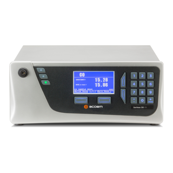
Ecotech Acoem Serinus 30 User Manual (225 pages)
Carbon Monoxide Analyser
Brand:
Ecotech
| Category:
Measuring Instruments
| Size: 9 MB
Table of Contents
Table of Contents
3
Manufacturer's Statement
12
Notice
12
Safety Information
13
Table 1 - Internationally Recognised Symbols
13
Warranty
15
Service & Repairs
16
Product Compliance and Approvals
17
Manual Revision History
18
Table 2 - Manual Revision History
18
1 Introduction
21
Description
21
Specifications
21
Measurement
21
Precision/Accuracy
21
Calibration
22
Power
22
Operating Conditions
22
Communications
23
Physical Dimensions
23
Certifications
23
Nomenclature
24
Background/Theory
25
Measurement Theory
25
Kalman Filter Theory
26
Figure 1 - Measurement Cell Theory
26
Figure 2 - Correlation Wheel
26
Instrument Description
27
Calibration Valve Manifold
27
Figure 3 - Internal Components Diagram
27
Figure 4 - Calibration Valve Manifold
27
Sample Filter Holder
28
CO-CO 2 Converter
28
Figure 5 - Sample Filter Holder
28
Figure 6 - CO-CO 2 Converter
28
Measurement Cell
29
Figure 7 - Measurement Cell
29
Figure 8 - Source Timing Assembly
29
Figure 9 - IR Source
30
Figure 10 - Gas Filter Correlation Wheel Assembly
30
Figure 11 - Detector Assembly
31
Figure 12 - Narrow-Bandpass Filter
31
Figure 13 - IR Detector
31
Figure 14 - CO Detector PCA
32
Figure 15 - Pressure Sensor PCA
32
Main Controller PCA
33
Pneumatic Tubing
33
Figure 16 - Heater and Thermistor
33
Figure 17 - Orifice and Sintered Filter
33
Figure 18 - Ecotech Tubing
33
Rear Panel
34
Figure 19 - Rear Panel
34
Figure 20 - Power ON/OFF Switch
34
Communications
35
Figure 21 - Communication Connections
35
2 Installation/Decommission
37
Initial Check
37
Table 3 - List of Items Received
37
Figure 22 - Received Item
38
Figure 23 - Opening the Instrument - 1
39
Figure 24 - Opening the Instrument - 2
39
Figure 25 - Opening the Instrument - 3
39
Installation Notes
40
Figure 26 - Opening the Instrument - 4
40
Instrument Set-Up
41
Power Connections
41
Figure 27 - Instrument Rear Panel
41
Pneumatic Connections
42
Figure 28 - Connect Power Cord
42
Figure 29 - Turn on Power Switch
42
Figure 30 - Dust Plugs
43
Figure 31 - Remove Nut
43
Figure 32 - Ferrules Correct Orientation
43
Figure 33 - Replace Nut Loosely
44
Figure 34 - Insert Tube
44
Figure 35 - Tighten Nut
44
Communications Connections
45
Instrument Set-Up
46
Figure 36 - Installation of USB Memory Stick
46
Figure 37 - Travel Screw Locations
46
Figure 38 - Switching the Battery ON/OFF
46
EPA Reference Set-Up
47
Type Approval Set-Up
48
Transporting/Storage
49
Figure 39 - Dust Plugs
49
Figure 40 - Packing Instruction
50
3 Operation
51
Warm-Up
51
Measurement
51
Table 4 - Measurements: Background and Sample Cycles
51
General Operation Information
52
Keypad & Display
52
Figure 41 - Front Panel
52
Table 5 - Front Panel Buttons Function
52
Home Screen
54
Figure 42 - Home Screen
54
Menus & Screens
56
Quick Menu
57
Figure 43 - Quick Menu Screen
57
Main Menu
58
Figure 44 - Main Menu Screen
58
Analyser State Menu
59
Figure 45 - Analyser State Menu Screen
59
Status Menu
60
Figure 46 - Status Menu Screen
60
Temperature Menu
61
Figure 47 - Temperature Menu Screen
61
Pressure & Flow Menu
62
Figure 48 - Pressure & Flow Menu Screen
62
Voltage Menu
63
Figure 49 - Voltage Menu Screen
63
General Settings Menu
64
Figure 50 - General Settings Menu Screen
64
Measurement Settings Menu
65
Figure 51 - Measurement Settings Menu Screen
65
Calibration Menu
66
Figure 52 - Calibration Menu Screen
66
Pressure Calibration Menu
68
Figure 53 - Pressure Calibration Menu Screen
68
Flow Calibration Menu (Option)
69
Figure 54 - Flow Calibration Menu Screen
69
Service Menu
70
Figure 55 - Service Menu Screen
70
Diagnostics Menu
71
Digital Pots Menu
71
Figure 56 - Diagnostics Menu Screen
71
Figure 57 - Digital Pots Menu Screen
72
Internal Pump Menu (Option)
73
Figure 58 - Internal Pump Menu Screen
73
Valve Menu
74
Figure 59 - Valve Menu Screen
74
Tests Menu
75
Digital Input Test Menu
75
Figure 60 - Tests Menu Screen
75
Figure 61 - Digital Input Test Menu Screen
75
Digital Output Test Menu
76
Calculation Factors Menu
76
Figure 62 - Digital Output Test Menu Screen
76
Figure 63 - Calculation Factors Menu Screen
76
Communications Menu
78
Data Logging Menu
78
Figure 64 - Communications Menu Screen
78
Figure 65 - Data Logging Menu Screen
78
Serial Communication Menu
79
Figure 66 - Serial Communication Menu Screen
79
Analog Input Menu
80
Figure 67 - Analog Input Menu Screen
80
Analog Output Menu
81
Figure 68 - Analog Output Menu Screen
81
Digital Input Menu
83
Figure 69 - Digital Input Menu Screen
83
Digital Output Menu
84
Figure 70 - Digital Output Menu Screen
84
Table 6 - Digital Output States
84
Network Menu (Option)
85
Figure 71 - Network Menu Screen
85
Bluetooth Menu
87
Trend Display Menu
87
Figure 72 - Bluetooth Menu Screen
87
Figure 73 - Trend Display Menu Screen
87
Chart
88
Figure 74 - Chart Screen
88
Advanced Menu
90
Figure 75 - Advance Menu Screen
90
Hardware Menu
91
Figure 76 - Hardware Menu Screen
91
Parameter Display Menu
92
Figure 77 - Parameter Display Menu Screen
92
4 Communications
93
RS232 Communication
93
Figure 78 - Communication Ports
93
USB Communication
94
Figure 79 - Multidrop RS232 Cable Example
94
TCP/IP Network Communication (Optional)
95
Figure 80 - Example of Typical Network Setups
95
Reading Network Port Setup
96
Setting Network Port Setup
96
Figure 81 - Example of Network Menu Setup
97
Figure 82 - Port Forwarding Example
97
Port Forwarding on Remote Modem/Router Setup
97
Airodis Setup to Communicate with Serinus
98
Figure 83 - LAN Network Set-Up (Airodis)
98
Figure 84 - WAN Network Set-Up (Airodis)
98
Analog and Digital Communication
99
Analog Outputs
99
Analog Inputs
100
Digital Status Inputs
100
Digital Status Outputs
100
Figure 85 - 25 Pin Rear Panel PCA (Default Jumpers Highlighted)
100
Logging Data
101
Configure Instrument Internal Logging
101
Figure 86 - Analog & Digital I/O Individual Pin Descriptions
101
Using Airodis Software to Download Data
102
Connecting the Instrument to a PC
102
Figure 87 - Installing Driver Software (Device Manager)
102
Figure 88 - Update Driver Popup
103
Figure 89 - Update Driver Popup (Directory Location)
103
Figure 90 - Installing Driver Confirmation Prompt
104
Figure 91 - Successful Driver Installation
104
Installing Airodis
105
Configuring Airodis
105
Figure 92 - Airodis Workspace Manager
105
Figure 93 - Adding a New Station
106
Figure 94 - New Station Connection
106
Table 7 - New Station Setup
106
Figure 95 - Station Configuration (Channel List)
107
Figure 96 - Error Status Notification
108
Figure 97 - Downloading Data
108
Figure 98 - Download Data Status
109
Figure 99 - Data Visibility
109
Figure 100 - Exporting Data
110
Figure 101 - Data Download Complete
110
Serinus Remote App/Bluetooth
111
Installation
111
Connecting to the Instrument
111
Figure 102 - Downloading the App from Google Play Store
111
Instrument Control
112
Figure 103 - Bluetooth Pairing Request
112
Figure 104 - Showing or Hiding the Numpad
113
Figure 105 - Switching Analysers
113
Real-Time Plot
114
Figure 106 - Real-Time Plot
114
Download
115
Get Parameters
115
Figure 107 - Plot of Downloaded Data
115
Preferences
116
Figure 108 - Directory Settings
116
Figure 109 - Logs Format
116
Figure 110 - Colour Theme Settings
117
5 Calibration
119
Overview
119
Figure 111 - Example of a Calibration System
119
Pressure Calibration
121
Full Pressure Calibration (Two Point Calibration)
121
Figure 112 - Full Pressure Calibration Set-Up
122
Figure 113 - Full Pressure Calibration Set-Up (Ambient)
122
Pressure Calibration (Ambient Only)
123
Pressure Calibration (Internal Pump Option Only)
123
Figure 114 - Ambient Pressure Calibration Set-Up
123
Figure 115 - Pressure Calibration (Internal Pump Option Only) Set-Up
124
Manual Background
125
Zero Calibration
125
Calibration Port
125
Sample Port
126
Figure 116 - Zero Calibration Set-Up - 1
126
Figure 117 - Zero Calibration Set-Up - 2
126
Background Air Port
127
Span Calibration
127
Calibration Port
128
Figure 118 - Span Calibration Set-Up - 1
128
Sample Port
129
Manual Instrument Gain and Offset Adjustments
129
Figure 119 - Span Calibration Set-Up - 2
129
Precision Check
130
Multipoint Precision Check
130
Flow Calibration (Internal Pump Option Only)
132
Figure 120 - Excel Graph of Multipoint Precision Check
132
High Pressure Zero/Span Valve (Option)
133
Single Pressurised Calibration Option
134
Figure 121 - Single High Pressure Calibration Option
134
Dual Pressurised Calibration Option
135
Figure 122 - Dual High Pressure Calibration Option
135
6 Service
139
Additional Safety Requirements for Service Personnel
139
Maintenance Tools
139
Figure 123 - Minifit Extraction Tool - (PN: T030001)
140
Figure 124 - Orifice/Sintered Filter Removal Tool - (PN: H010046)
140
Figure 125 - Leak Test Jig - (PN: H050069)
140
Figure 126 - Air Monitoring Test Equipment Kit (AMTEK) - Customisable
140
Maintenance Schedule
141
Table 8 - Maintenance Schedule
141
Table 16 - Maintenance Schedule
141
Maintenance Procedures
142
Particulate Filter Replacement
142
Figure 127 - Remove Kynar Nut
142
Figure 128 - Remove Retaining Ring
142
Figure 129 - Remove Filter Sealing Cap
143
Figure 130 - Particulate Filter
143
Figure 131 - Avoid to Touching Particulate Filter Paper
144
Clean Chassis Fan Filter
145
Figure 132 - Kynar Elbow Barb Fitting Direction
145
Figure 133 - Remove Filter Casing and Filter
145
DFU Replacement
146
Leak Check
146
Figure 134 - Remove Kynar Nut
146
Figure 135 - Leak Test Jig on Exhaust Port
147
Figure 136 - Connect Vacuum Source
147
Figure 137 - Kynar Blocker Nut
147
CO-CO 2 Converter Check
151
Sintered Filter/Orifice Replacement
152
Figure 138 - Kynar Fitting Containing Orifice and Sintered Filter
152
Figure 139 - Remove Orifice and Sintered Filter
152
Trim Pot Tuning Procedure
153
Figure 140 - Adjust Trim Pot
153
Clean Pneumatics
154
Pressure Sensor Check
154
Bootloader
155
Display Help Screen
155
Communications Port Test
155
Updating Firmware
155
Figure 141 - Test Point Location
155
Erase All Settings
156
Start Analyser
156
7 Troubleshooting
158
Table 9 - Troubleshoot List
158
Flow Fault
162
Figure 142 - Flow Fault Diagnostic Procedure
162
Noisy/Unstable Readings
163
Figure 143 - Noisy Zero or Unstable Span Diagnostic Procedure
163
Cell Temperature Failure
164
Figure 144 - Cell Temperature Failure Diagnostic Procedure
164
Mirror Temperature Failure
165
Figure 145 - Mirror Temperature Failure Diagnostic Procedure
165
USB Memory Stick Failure
166
Figure 146 - USB Memory Stick Failure
166
Ecotech Service Support Files
167
Figure 147 - USB Memory Stick File Structure
168
8 Optional Extras
170
Dual Sample Filter (PN: E020100)
170
Network Port (PN: E020101)
170
Figure 148 - Dual Filter Option Installed
170
Hardware Setup
171
Rack Mount Kit (PN: E020116)
171
Table 10 - Included Parts (Rack Mount Kit)
171
Figure 149 - Separate Rack Slides
172
Figure 150 - Assemble Inner Slide on Chassis
172
Figure 151 - Rack Mount Ears Fitted to Instrument
173
Figure 152 - Attach Rack Mount Adaptors to Outer Slides
173
Figure 153 - Test Fit the Rack Slide Assembly into the Rack
174
Figure 154 - Attach Slides to Front of Rack
174
Internal Pump (PN: E020107)
175
Hardware Setup
175
Figure 155 - Slide Clips
175
Internal Pump Additional Components
176
Internal Pump Removed Components
176
Pressure Calibration Internal Pump Option
176
Table 11 - Internal Pump Additional Components
176
Table 12 - Internal Pump Removed Components
176
Flow Calibration
177
Internal Pump Leak Check
177
Pump Control
177
Metric Fittings Kit (PN: E020122)
177
High Pressure Zero/Span Valves
177
Trace Level Instrument (PN: E020127)
178
Trace Specifications
178
Measurement
178
Precision/Accuracy
178
Calibration
178
Table 13 - Trace Parts Removed
178
Table 14 - Trace Parts Added
178
Trace Setup
179
Trace Operation
179
Trace Default Values
180
Trace Calibration Guidelines
180
Table 15 - Trace Parameter Value Changes
180
Trace Service and Maintenance
181
External CO Sensor (PN: E031014)
182
Introduction
182
Specifications
182
Figure 156 - External CO Sensor
182
Equipment Required
183
Installation
183
Figure 157 - Wiring Connections - CO Probe to CO Analyser
184
Figure 158 - Example of Installed CO Sensor
184
Operation
185
Maintenance
185
Troubleshooting
185
9 Parts List and Schematics
186
Serinus Accessories Kit
186
Maintenance Kit
186
Table 17 - Serinus Accessories Kit - (PN: H010136)
186
Table 18 - Serinus 30 Maintenance Kit - (PN: E020202)
186
Consumables
187
Instrument Parts List
187
Table 19 - Serinus 30 Consumables
187
Table 20 - Spare Parts List (Main Components)
187
Table 21 - Spare Parts List (Cables)
188
Table 22 - Spare Parts List (O-Rings)
189
Table 23 - Spare Parts List (Fittings)
189
Table 24 - Spare Parts List (Miscellaneous)
190
Table 25 - Spare Parts List (Shipping)
190
Table 26 - Spare Parts List (External CO Sensor)
191
Plumbing Schematic - (PN: D020005)
192
Block Wiring Schematic - (PN: D020102)
193
Measurement Cell - (PN: H014100)
194
Source Timing Assembly - (PN: H014125)
195
Calibration Manifold Assembly - (PN: H010013-01)
196
Valve Assembly - (PN: H010042)
197
High Pressure Valve Exploded View - (PN: H050043)
198
Sample Filter Holder Assembly - (PN: H010160)
199
CO-CO Converter Assembly - (PN: H014130)
200
Table 27 - Packet Format
202
Table 28 - Example: Primary Gas Request
202
Appendix A. Advanced Protocol
202
Command Format
202
Table 29 - Example: Primary Gas Response
203
Table 30 - Example: Primary Gas Response (Continued)
203
Table 31 - List of Errors
203
Commands
203
Table 32 - Example: Get IEEE Response Data
204
Table 33 - Advanced Protocol Parameter List
205
List of Parameters
205
Appendix B. EC9800 Protocol
216
Command Format
216
Commands
216
Table 34 - Bayern-Hessen Data
218
Appendix C. Bayern-Hessen Protocol
218
Command Format
218
Table 35 - Block Check Operation
219
Commands
219
Table 36 - Status Bit Map
220
Table 37 - Failure Bit Map (Positive Logic)
221
Appendix D. Modbus Protocol
222
Command Format
222
Commands
223
Table 38 - Modbus Error Codes
224
Advertisement
Advertisement
Related Products
Ecotech Acoem Serinus 10
Ecotech A Series
Ecotech B Series
Ecotech EC9830
Ecotech EC9830B
Ecotech HiVol 3000
Ecotech Serinus 30
Ecotech Serinus 40
Ecotech Serinus 44
Ecotech Serinus 51
Ecotech Categories
Measuring Instruments
Security Sensors
Monitor
Brush Cutter
Receiver
More Ecotech Manuals
Login
Sign In
OR
Sign in with Facebook
Sign in with Google
Upload manual
Upload from disk
Upload from URL