
Related Manuals for STF-Filtros FMA-3000


Summary of Contents for STF-Filtros FMA-3000
- Page 1 Installation, Operation and Maintenance Manual – FMA 3000 FMA – 3000 INSTALLATION, OPERATION AND MAINTENANCE MANUAL Ref: 3000/T/6/VH Ref: 3000/T/6/VH...
-
Page 2: Table Of Contents
Installation, Operation and Maintenance Manual – FMA 3000 CONTENTS 1. – INTRODUCTION...........................6 2. – WARRANTY..........................7 3. – SAFETY............................8 4. – DESCRIPTION OF FILTER FMA-3000 ..................10 5. –FMA-3000 OPERATION ......................12 6. – TECHNICAL CHARACTERISTICS................... 13 7. – NAMEPLATE..........................18 8. – INSTALLATION INSTRUCTIONS..................... 19 9. - Page 3 Installation, Operation and Maintenance Manual – FMA 3000 IMPORTANT NOTICE READ AND FOLLOW THE INSTRUCTIONS IN THIS MANUAL BEFORE INSTALLATION OR ASSISTANCE IN THE DEVICE. THE MANUFACTURER WILL NOT BE LIABLE FOR ANY DAMAGE THAT MAY RESULT, EVEN FOR NEGLIGENCE CAUSED BY NOT READING THE MANUAL This appliance has been designed so that it does not cause any risk during the use for which it has been designed, provided that: Both the installation and management and maintenance are carried out in accordance with the...
- Page 4 Installation, Operation and Maintenance Manual – FMA 3000 WARNING! RISK OF ELECTRIC SHOCK. THE OPERATIONS MARKED WITH THIS SYMBOL MUST ONLY BE PERFORMED BY QUALIFIED PERSONNEL WARNING! ESSENTIAL INFORMATION AND ISSUES. PLEASE REFER TO THE DOCUMENTATION ACCOMPANYING THE DEVICE. NOTE VERY IMPORTANT INFORMATION AND ISSUES.
- Page 5 Installation, Operation and Maintenance Manual – FMA 3000 Ref: 3000/T/6/VH...
-
Page 6: Introduction
All products manufactured by STF - FILTROS are easy to install, use and maintain. Should you have any questions about the operation after reading this manual, please contact STF-Filtros technical department. CONTACT SISTEMA DE FILTRADO Y TRATAMIENTO DE FLUIDOS S.A ... -
Page 7: Warranty
Installation, Operation and Maintenance Manual – FMA 3000 2. – WARRANTY Ref: 3000/T/6/VH... -
Page 8: Safety
Installation, Operation and Maintenance Manual – FMA 3000 3. – SAFETY INSTRUCTIONS FOR THE SAFE USE OF THE FILTER MISUSE AND IMPROPER MAINTENANCE OF THIS DEVICE CAN CAUSE INJURY TO USERS. TO AVOID THESE RISKS, YOU ARE STRONGLY ADVISED TO FOLLOW THE INSTRUCTIONS BELOW. - Page 9 Installation, Operation and Maintenance Manual – FMA 3000 Check that screws, bolts and the cover are firmly fastened. Regularly check they are tight. Operate the device at nominal voltage. Bear in mind the voltage specified in this manual and on the filter nameplate. ...
-
Page 10: Description Of Filter Fma-3000
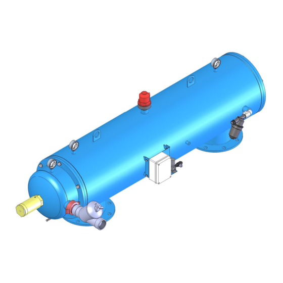
Installation, Operation and Maintenance Manual – FMA 3000 4. – DESCRIPTION OF FILTER FMA-3000 The filter consists of an outer casing which houses three distinct chambers. The first one is a prefiltering chamber which coincides with the filter water inlet, and where the Coarse Mesh is located, the second one is a FILTERING CHAMBER where the fine mesh is located and where the filtering process takes place and the third one, which is a cleaning chamber. - Page 11 Installation, Operation and Maintenance Manual – FMA 3000 reaching a few microns away from the mesh. The location of these nozzles in the suction scanner has been designed to come into contact with the entire inner surface of the mesh, thanks to the spiral movement provided to the scanner by the electric motor by combining longitudinal displacement and rotation.
-
Page 12: Fma-3000 Operation
Installation, Operation and Maintenance Manual – FMA 3000 5. –FMA-3000 OPERATION Water enters the filter through the roughing chamber, which works like a stone trap where any coarse particles are retained. The water flows outwards through the FINE MESH, thus producing SURFACE MECHANICAL FILTRATION. -
Page 13: Technical Characteristics
Installation, Operation and Maintenance Manual – FMA 3000 6. – TECHNICAL CHARACTERISTICS Flow rates are calculated for a filtration rate of 125 microns, please consult about others. Ref: 3000/T/6/VH... - Page 14 Installation, Operation and Maintenance Manual – FMA 3000 MODEL 3003 3004 3006 3008 3010 GENERAL FEATURES Diameter Inlet/Outlet DN-80 (3”) DN-100 (4”) DN-150 (6”) DN-200 (8”) DN-250 (10”) Max./mín. working pressure 2 bar / 10 bar (please consult about others) Max.
- Page 15 Installation, Operation and Maintenance Manual – FMA 3000 STANDARD MATERIALS Filter body and caps S-235-JR Carbon steel Finish treatment Oven-cured epoxy polyester powder paint coating Suction scanner AISI-304 Stainless steel Filtering mesh AISI-316 Stainless steel Suction nozzle PVC with AIS 316 stainless steel ring and nylon bristles Cleaning valves Polypropylene Screws...
- Page 16 Installation, Operation and Maintenance Manual – FMA 3000 STANDARD MATERIALS Filter body and caps S-235-JR Carbon steel Finish treatment Oven-cured epoxy polyester powder paint coating Suction scanner AISI-304 Stainless steel Filtering mesh AISI-316 Stainless steel Suction nozzle PVC with AIS 316 stainless steel ring and nylon bristles Cleaning valves Polypropylene Spacer disc...
- Page 17 Installation, Operation and Maintenance Manual – FMA 3000 Ref: 3000/T/6/VH...
-
Page 18: Nameplate
Installation, Operation and Maintenance Manual – FMA 3000 7. – NAMEPLATE All devices are identified by means of a nameplate pasted on the filter. It includes the following data: Device series. Model. Serial number of the device in question. ... -
Page 19: Installation Instructions
Installation, Operation and Maintenance Manual – FMA 3000 8. – INSTALLATION INSTRUCTIONS Take any necessary precautions to prevent bumping the filter. Lift the device by using the anchoring points at the top. Make sure the installation point has the minimum operating pressure. o The discharge pipe should be dimensioned to generate a minimum pressure loss at a flow rate of 30 m³/h. - Page 20 Installation, Operation and Maintenance Manual – FMA 3000 CLEANING TIME DEPENDING ON WORKING PRESSURE, YOU MUST SET A CLEANING TIME ON THE PROGRAMMING UNIT (SEE ATTACHED CHART). RANGE OF PRESSURES Kg/cm2 TIME 45 seconds 30 seconds 25 seconds 20 seconds ...
-
Page 21: Start-Up Instructions
Installation, Operation and Maintenance Manual – FMA 3000 9. – START-UP INSTRUCTIONS Check the items in the section above. Check the hydraulic circuit (see section 14) which brings water to the flush valve, making sure that: o The filter is clean. ... -
Page 22: Maintenance Instructions
Installation, Operation and Maintenance Manual – FMA 3000 10. – MAINTENANCE INSTRUCTIONS. Disconnect the filter from the power supply before performing any maintenance operation. Make sure the filter is depressurized before loosening the screws. Avoid splashing and water loss, thus minimizing the risk of staff electrocution or slipping as well as the damage that moisture can cause to your device. -
Page 23: Preventive Maintenance Schedule
Installation, Operation and Maintenance Manual – FMA 3000 11. – PREVENTIVE MAINTENANCE SCHEDULE MAINTENANCE FREQUENCY ITEM ACTION EXTERNAL Manual cleaning cycle. Check: Check operation 6 months Entire filter Hydraulic piston drainage. Open valve. Effective cleaning cycle (achieve P Review anticorrosion treatment on required points. -
Page 24: Control Panel
Installation, Operation and Maintenance Manual – FMA 3000 12. – CONTROL PANEL When an FMA-1000 model filter is supplied, all electrical connections between the control panel, the sensors and the actuators have already been installed and tested by the manufacturer. Standard power of the device is 6V DC. - Page 25 Installation, Operation and Maintenance Manual – FMA 3000 Differential pressure setpoint. Differential pressure setpoint. Standard: 0.3 bar (0.1.0.0) Standard: 12 hours (1.1.0.1) Cleaning cycle duration. Standard: 20 seconds Batteries Ref: 3000/T/6/VH...
-
Page 26: Connection
Installation, Operation and Maintenance Manual – FMA 3000 12.1. – CONNECTION WARNING! RISK OF ELECTRIC SHOCK. THE OPERATIONS MARKED WITH THIS SYMBOL MUST ONLY BE PERFORMED BY QUALIFIED PERSONNEL The device’s power supply, sensors and actuators are connected to the lower terminals according to the following specification: ... -
Page 27: Operation
Installation, Operation and Maintenance Manual – FMA 3000 12.2. – OPERATION The programming unit controls automatic cleaning of one filter. Cleaning can be started in three ways: Manual cleaning. You must hold the manual cleaning button for 5 seconds. ... -
Page 28: Changing Settings
Installation, Operation and Maintenance Manual – FMA 3000 12.3. – CHANGING SETTINGS You must access the electronic board in order to change the manufacturer's settings. SELECTING THE INTERVAL BETWEEN CLEANING OPERATIONS The interval between cycles is controlled by the S1 selector. The following table shows the different possibilities: INTERVAL BETWEEN CLEANING OPERATIONS... - Page 29 Installation, Operation and Maintenance Manual – FMA 3000 SELECTING CLEANING TIME Filter cleaning time is controlled by the S2 selector. The following table shows the different possibilities: CLEANING TIME 1 – ON Position 0 – OFF TIME 1 2 3 4 0 0 0 0 5 seconds 1 0 0 0...
- Page 30 Installation, Operation and Maintenance Manual – FMA 3000 ADJUSTING THE SETPOINT OF THE DIFFERENTIAL PRESSURE SENSOR The differential pressure sensor is regulated by the S3 selector block as shown in the following table. While the differential pressure is maintained below the setpoint, no cycle start signal is generated, but when the differential pressure is greater, it works as a closed contact in the differential pressure sensor and a cleaning cycle will be initiated if this condition is maintained for at least 5 seconds.
- Page 31 Installation, Operation and Maintenance Manual – FMA 3000 THE ROLE OF JUMPERS JP1, JP7, JP8, JP9 Can only be used for initial calibration. During normal operation the left pin in the jumper is free. Switch between 6 V or 12 V power supply. When the left pin in the jumper is free, 12 V power has been selected.
-
Page 32: Notices And Alarms
Installation, Operation and Maintenance Manual – FMA 3000 13. – NOTICES AND ALARMS 1 beep every 15 seconds – Normal operation. 2 beeps every 15 seconds – Continuous cleaning problem alarm. 3 beeps every 15 seconds – Low battery. ... -
Page 33: Hydraulic Circuit
Installation, Operation and Maintenance Manual – FMA 3000 14. – HYDRAULIC CIRCUIT The filter has a hydraulic valve which is resposnible for evacuating the cleaning flow. The valve remains closed by action of an internal spring and the water pressure in the valve chamber, it opens when the water in the chamber is drained, and closes when it is filled. - Page 34 Installation, Operation and Maintenance Manual – FMA 3000 WARNING! MAINTENANCE OF FILTER THAT PROTECTS THE CIRCUIT, BY PERFORMING REGULAR CLEANING. LONG DISTANCE DRAINAGE MAY RESULT IN OPERATION PROBLEMS. NOTE THE DIAGRAM ABOVE IS VALID FOR STANDARD DEVICES WITH MAXIMUM PRESSURE OF 10 BAR. PLEASE CONSULT THE MANUFACTURER ABOUT OTHER PRESSURES.
-
Page 35: Parts
Installation, Operation and Maintenance Manual – FMA 3000 15. – PARTS Position Device Model Description FMA-3004 - FMA-3010 M12 L=150 Rod FMA-3004 FMA-3004 Housing FMA-3006 FMA-3006 Housing FMA-3008 FMA-3008 Housing FMA-3010 FMA-3010 Housing FMA-3004 - FMA-3010 Gas 1/4" Plug Glycerine Gauge FMA-3004 - FMA-3010 Gas 1"... - Page 36 Installation, Operation and Maintenance Manual – FMA 3000 Position Device Model Description FMA-3004 M8 Nut FMA-3006 M8 Nut 15.11 FMA-3008 M8 Nut FMA-3010 M8 Nut FMA-3004 M8x30 Screw FMA-3006 M8x30 Screw 15.12 FMA-3008 M8x30 Screw FMA-3010 M8x30 Screw FMA-3004 Hair-filtering Nozzle FMA-3006 Hair-filtering Nozzle 15.13...
- Page 37 Installation, Operation and Maintenance Manual – FMA 3000 Position Device Model Description FMA-3004 - FMA-3010 NO Latching Solenoid (battery box) FMA-3004 - FMA-3010 NO 24v 50Hz Solenoid (220v box) FMA-3004 - FMA-3010 M6 Nut FMA-3004 - FMA-3010 M6 Washer FMA-3004 - FMA-3010 M6x15 Screw Ref: 3000/T/6/VH...
- Page 38 Installation, Operation and Maintenance Manual – FMA 3000 Ref: 3000/T/6/VH...
- Page 39 Installation, Operation and Maintenance Manual – FMA 3000 Ref: 3000/T/6/VH...
-
Page 40: Error Detection And Troubleshooting
Installation, Operation and Maintenance Manual – FMA 3000 16. – ERROR DETECTION AND TROUBLESHOOTING Ref: 3000/T/6/VH... - Page 41 Installation, Operation and Maintenance Manual – FMA 3000 Sistemas de Filtrado y Tratamientos de Fluidos S.A. Pol. Armentera Parc. 87 22400 Monzón (Huesca / Spain) Tel: +34 974 401 933 Fax: +34 974 417 809 info@stf.filtros.com www.sft-filtros.com Ref: 3000/T/6/VH...
Need help?
Do you have a question about the FMA-3000 and is the answer not in the manual?
Questions and answers