
Related Manuals for STF-Filtros FMA-2000 series


Summary of Contents for STF-Filtros FMA-2000 series
- Page 1 Installation, operation and maintenance manual - FMA 2000 FMA – 2000 INSTALLATION, OPERATION AND MAINTENANCE MANUAL Ref: 2000/CPF01/230/VH Ref: 2000/CPF01/230/VH...
-
Page 2: Table Of Contents
Installation, operation and maintenance manual - FMA 2000 TABLE OF CONTENTS: 1. – INTRODUCTION ....................... 6 2. – WARRANTY ......................7 3. – SAFETY ........................8 4. –FMA-2000 FILTER DESCRIPTION ................10 5. – FMA-2000 PERFORMANCE ..................11 6. – TECHNICAL CHARACTERISTICS ................12 7. - Page 3 Installation, operation and maintenance manual - FMA 2000 IMPORTANT WARNINGS READ CAREFULLY AND FOLLOW THE DEVICE MANUAL INSTRUCTIONS. THE MANUFACTURER IS NOT RESPONSIBLE FOR THE DAMAGES OCCURED OR THE NEGLIGENCES HAPPENED AS A RESULT OF NOT READING THE MANUAL This device has been manufactured in such a way that its performance does not bring about any risks for the designed usage, provided that: Both the installation and the management, as well as the maintenance have to be carried out according to the manual instructions.
- Page 4 Installation, operation and maintenance manual - FMA 2000 BEWARE! ELECTRICAL DISCHARGE RISK. THE OPERATIONS INDICATED WITH THIS SYMBOL WILL HAVE TO BE PERFORMED ONLY BY SKILLED TECHNICAL PERSONNEL BEWARE! ESSENTIAL INFORMATION AND ASPECTS. HAVE THE DEVICE DOCUMENTATION AS A REFERENCE. NOTE REALLY IMPORTANT INFORMATION AND ASPECTS.
- Page 5 Installation, operation and maintenance manual - FMA 2000 Ref: 2000/CPF01/230/VH...
-
Page 6: Introduction
If you have any doubts about its performance after reading this manual, please contact the STF- Filtros Technical Department. CONTACT SISTEMA DE FILTRADO Y TRATAMIENTO DE FLUIDOS S.A +34 974 401 933 +34 974 417 809 info@stf.filtros.com www.stf-filtros.com Ref: 2000/CPF01/230/VH... -
Page 7: Warranty
Installation, operation and maintenance manual - FMA 2000 2. – WARRANTY Ref: 2000/CPF01/230/VH... -
Page 8: Safety
Installation, operation and maintenance manual - FMA 2000 3. – SAFETY FILTER SAFE USE INSTRUCTIONS THE INCORRECT USE AND MAINTENANCE OF THE EQUIPMENT MAY CAUSE PHYSICAL INJURIES. IT IS STRONGLY RECOMMENDED TO RESPECT THE FOLLOWING INSTRUCTIONS IN ORDER TO AVOID RISKS. USE ACCIDENT PREVENTION MEASURES THAT GUARANTEE YOUR SAFETY AND THE EQUIPMENT SAFETY. - Page 9 Installation, operation and maintenance manual - FMA 2000 Make the equipment to run at a nonimal tension Pay attention to the specified voltage in this manual and the characteristics plate in the filter. Never use the filter if it is faulty. If the filter runs making weird noises, a lot of vibrations or it looks faulty, stop its running immediately and check its functionality.
-
Page 10: Fma-2000 Filter Description
Installation, operation and maintenance manual - FMA 2000 4. –FMA-2000 FILTER DESCRIPTION The filter consists of an external casing where there are three different chambers. There is a coarse screen that is used as a prefilter in the first prefiltration chamber that coincides with the water inlet. -
Page 11: Fma-2000 Performance
Installation, operation and maintenance manual - FMA 2000 5. – FMA-2000 PERFORMANCE Water gets into the filter through the prefiltration chamber, where thick particles are retained, as it was a strainer. Water gets into the filtering chamber, goes through from inside to outside the FILTERING SCREEN, producing the SURFACE MECHANIC. -
Page 12: Technical Characteristics
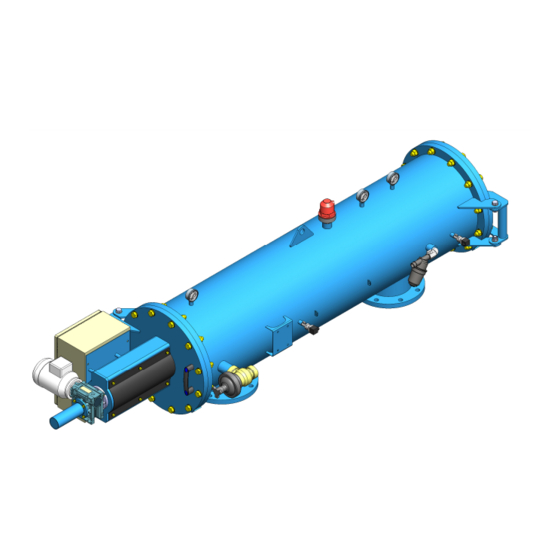
Installation, operation and maintenance manual - FMA 2000 6. – TECHNICAL CHARACTERISTICS 1 – Automatic filter Series 2000 2 – Butterfly valve inlet 3 – By-Pass valve 4 – Butterfly valve outlet 5 – Cleaning valve 2” 6 – Retaining valve (optional) 1 –... - Page 13 Installation, operation and maintenance manual - FMA 2000 Filter model STF - FMA 2003 2004 2006 2008 2010 2012 2014 GENERAL CHARACTERISTICS DN-80 DN-100 DN-150 DN-200 DN-250 DN-300 DN-350 Inlet diameter /Outlet (3”) (4”) (6”) (8”) (10”) (12”) (14”) Maximum/ minimum working 2 bar / 10 bar (for other working pressure, please ask us ) pressure Fluid maximum temperature...
- Page 14 Installation, operation and maintenance manual - FMA 2000 STANDARD MATERIALS Filter body and covers S-235-JR Carbon steel Finish treatment Epoxi-polyester polymerized baked oven finish powder coating. Suction scanner AISI-304 stainless steel Filtration screen AISI-316 stainless steel Suction nozzles PVC with stainless steel AIS 316 ring and nylon fibers Backwashing valves Brass body with stainless steel spring and axis and polyamide cover.
- Page 15 Installation, operation and maintenance manual - FMA 2000 Ref: 2000/CPF01/230/VH...
- Page 16 Installation, operation and maintenance manual - FMA 2000 Ref: 2000/CPF01/230/VH...
-
Page 17: Identification Plate
Installation, operation and maintenance manual - FMA 2000 7. – IDENTIFICATION PLATE All the equipments are identified by means of an identification plate stuck to the filter. The following information is included in the identification plate: Equipment serial Model ... -
Page 18: Installation Instructions
Installation, operation and maintenance manual - FMA 2000 8. – INSTALLATION INSTRUCTIONS Take precautions to prevent the filter from striking, the equipment lifting by means of the upper anchor points. Make sure that the installation point has the minimum operation pressure. o The backwashing pipe has to be measured so that it gets a minimum flow head loss of 25 m³/h. -
Page 19: Starting Instructions
Installation, operation and maintenance manual - FMA 2000 9. – STARTING INSTRUCTIONS. Check previous section instructions. Check the hydraulic circuit (see section 15) that provides the backwashing valve with water, making sure that: o ¾” filter is clean. o The ball valve is open. - Page 20 Installation, operation and maintenance manual - FMA 2000 NOTE THE FILTER CAN START THE BACKWASHING CYCLE AUTOMATICALLY WHEN THE 0.3 PRESSURE DIFFERENCE BETWEEN THE INLET AND THE OUTLET RISES OVER 0.3 BAR. NOTE IN CASE OF HAVING SEVERAL FILTERS WORKING IN PARALEL WITH COMMON CONTROL PANEL, PLEASE NOTE THAN THE FILTER WHICH MANAGES THE CLEANING IS THE ONE WITH THE PRESSURE TRANSMITTERS / PRESSURE SWITH INSTALLED IN ITS BODY.
-
Page 21: Maintenance Instructions
Installation, operation and maintenance manual - FMA 2000 10. – MAINTENANCE INSTRUCTIONS. Switch off the enery supply filter before any maintenance operation. Make sure that the filter is unpressurized before loosening the screws. Avoid splashes and water leaks by minimizing the personnel risk sliding or being electrocuted and the damage that humidity can cause to the equipment. -
Page 22: Preventive Maintenance Schedule
Spindle Turret 6 months Clean and grease spindle both sides. (element 1.23) Use the grease supplied by STF-Filtros. Revise the waterlightness of the element 1.10. Replace the inside joints: Rim watertightness Ø45x4 o-ring seal (element 1.9) Rim watertightness 6 months ... -
Page 23: Control Panel
Installation, operation and maintenance manual - FMA 2000 12. – CONTROL PANEL When a FMA-2000 filter model is supplied, all the electrical connections between the control panel and the actuators have already been installed and checked by the manufacturer. The equipment supply is 230V CA, 50Hz in a standard way. In case of variants, this should be checked with the manufacturer BEWARE! DURING THE STARTING, IT SHOULD BE CHECKED THAT THE ENGINE... - Page 24 Installation, operation and maintenance manual - FMA 2000 Ref: 2000/CPF01/230/VH...
-
Page 25: Connection
Installation, operation and maintenance manual - FMA 2000 12.1. – CONNECTION BEWARE! ELECTRICAL DISCHARGE RISK. THE OPERATIONS INDICATED WITH THIS SYMBOL SHOULD BE CARRIED OUT ONLY BY SKILLED TECHNICAL STAFF. The supply, sensor and equipment actuators connection is carried out in the lower terminal block according to the following specifications: Ref: 2000/CPF01/230/VH... - Page 26 Installation, operation and maintenance manual - FMA 2000 Panel supply: PE – L – N Engine supply input: PE – 1 – 2 – 3 Electrovalve supply output: 4 – 5 Backwashing inlet/ external rearm: +24 – 6 ...
-
Page 27: Performance
Installation, operation and maintenance manual - FMA 2000 12.2. – PERFORMANCE The start screen shows the following information, the upper parameters...3.4... indicate the entry signals into the programmer. Paramater 1 – Manual backwashing pushbutton Parameter 2 – Pressure switch.(Pressure transducers are used by default) ... -
Page 28: Modifying Parameters
Installation, operation and maintenance manual - FMA 2000 12.3. –MODIFYING PARAMETERS It is useful to observe the diagram that is shown in order to have access to the different program functions. In the same diagram the main menu and several submenus appear. Pulse OK in order to have access to the main menu functions. - Page 29 Installation, operation and maintenance manual - FMA 2000 PASSWORD: It allows you to have access to the program, it is protected to avoid non- authorized modifications by the manufacturer. RUN / STOP: It allows you to stop the running cycle when the STOP key is pressed. The symbol ...
- Page 30 Installation, operation and maintenance manual - FMA 2000 S – Setpoint value C – Meter real value Press keys to move over S. Press OK to modify values by using keys and . When finished, press OK again to accept the new value. Press ESC to quit C16–...
- Page 31 Installation, operation and maintenance manual - FMA 2000 BEWARE! IT IS NOT ADVISABLE TO MODIFY THIS VALUE. THE DIFFERENTIAL SHOULD NEVER BE INCREASED, IT CAN ONLY BE MODIFIED TO LOWER VALUES IN ORDER TO BACKWASH. Ref: 2000/CPF01/230/VH...
-
Page 32: Warnings And Alarms
Installation, operation and maintenance manual - FMA 2000 13. – WARNINGS AND ALARMS 1. When the programmer makes the number of backwashings consecutively indicated in parameter C2 (the setpoint is 20) there is no possibility to go on filtering, the safety device that will stop the filter backwashing will activate. -
Page 33: Electric Diagram
Installation, operation and maintenance manual - FMA 2000 14. – ELECTRIC DIAGRAM Layout 1 of 2 Ref: 2000/CPF01/230/VH... - Page 34 Installation, operation and maintenance manual - FMA 2000 Layout 2 of 2 Ref: 2000/CPF01/230/VH...
-
Page 35: Hydraulic Circuit
Installation, operation and maintenance manual - FMA 2000 15. – HYDRAULIC CIRCUIT. The filter has a hydraulic valve for draining the backwashing flow. The valve remains closed because of the internal spring, and it opens when introducing water in the lower chamber and it closes when the drain is in process. - Page 36 Installation, operation and maintenance manual - FMA 2000 BEWARE! FILTER THAT PROTECTS THE CIRCUIT MAINTENANCE BY MEANS OF USUAL BACKWASHINGS. LONG DISTANCE DRAINAGE CONDUCTION CAN RESULT IN OPERATION PROBLEMS. NOTE THE PREVIOUS DIAGRAM IS VALID ONLY FOR STANDARD EQUIPMENTS WITH MAXIMUM 10 BAR PRESSURE ASK THE MANUFACTURER IN CASE OF DIFFERENT PRESSURES.
-
Page 37: Explosion Drawing
Installation, operation and maintenance manual - FMA 2000 16. – EXPLOSION DRAWING Order Equipment model Description Number of units TURRET FMA-2003 - 2014 Electric panel CPF-01 ( for 1 filter, 230v. ca panel ) FMA-2003 - 2014 Electric panel CPF-04 ( for 4 filters 230v. ca panel ) FMA-2003 - 2014 Electric panel CPF-10 ( for 10 filters 230v. - Page 38 Installation, operation and maintenance manual - FMA 2000 Order Equipment model Description Number of units FMA-2003 - 2010 M18 washer FMA-2012 / 2014 M24 washer FMA-2003 - 2014 M16 washer FMA-2003 - 2014 M16x50 screw FMA-2003 - 2014 M16 nut FMA-2003 - 2014 Glycerin pressure gauge Macho Gas-1/4"...
- Page 39 Installation, operation and maintenance manual - FMA 2000 Order Equipment model Description Number of units SCANNER FMA-2003 Nylon brushes nozzle FMA-2004 Nylon brushes nozzle 24.1 FMA-2006 Nylon brushes nozzle FMA-2008 / 2012 Nylon brushes nozzle FMA-2010 / 2014 Nylon brushes nozzle FMA-2003 3/4"...
- Page 40 Installation, operation and maintenance manual - FMA 2000 Order Equipment model Description Number of units FILTRATION CARTRIDGE PVC screen cartridge ….. Micron FMA-2003 INOX screen cartridge …. Micron PVC screen cartridge ….. Micron FMA-2004 INOX screen cartridge …. Micron PVC screen cartridge ….. Micron FMA-2006 INOX screen cartridge ….
- Page 41 Installation, operation and maintenance manual - FMA 2000 Ref: 2000/CPF01/230/VH...
- Page 42 Installation, operation and maintenance manual - FMA 2000 Ref: 2000/CPF01/230/VH...
- Page 43 Installation, operation and maintenance manual - FMA 2000 Ref: 2000/CPF01/230/VH...
- Page 44 Installation, operation and maintenance manual - FMA 2000 Ref: 2000/CPF01/230/VH...
-
Page 45: Error Detection
Installation, operation and maintenance manual - FMA 2000 17. – ERROR DETECTION (*) C1 – Pressure switch selection differential & pressure transducers. Se programmer panel / Modify parameters. (**) T8 – Time between backwashings. See programmer panel / Modify parameters. Ref: 2000/CPF01/230/VH... - Page 46 Installation, operation and maintenance manual - FMA 2000 (***) – See hydraulic circuit section. (****) C2 – Consecutive pieces counter. See programmer panel section / Modify parameters Ref: 2000/CPF01/230/VH...
- Page 47 Installation, operation and maintenance manual - FMA 2000 Sistemas de Filtrado y Tratamientos de Fluidos S.A. Pol. Armentera Parc. 87 22400 Monzón (Huesca / Spain) Tel: +34 974 401 933 Fax: +34 974 417 809 info@stf.filtros.com www.sft-filtros.com Ref: 2000/CPF01/230/VH...
Need help?
Do you have a question about the FMA-2000 series and is the answer not in the manual?
Questions and answers