Table of Contents
Advertisement
Quick Links
Advertisement
Table of Contents

Related Manuals for VOLTCRAFT VC-7055BT


Summary of Contents for VOLTCRAFT VC-7055BT
- Page 1 VC-7055BT Digital Multimeter User Manual...
-
Page 2: Table Of Contents
Table of Contents 1.Safety Information......................1 Safety Terms and Symbols......................1 General Safety Requirements......................2 Measurement Limits........................3 Main Input Terminals (HI Input and LO Input) Measurement Limits............3 Current Input Terminal (I) Measurement Limits..................3 Sense Terminals (HI Sense and LO Sense) Measurement Limits...............4 Measurement Category......................... - Page 3 Backlight..............................28 Clock.................................28 Default..............................28 4.Measurement Tutorial.....................30 Loading Errors (DC Voltage)......................30 True RMS AC Measurements.......................31 Loading Errors (AC Voltage)......................32 Crest Factor Errors (non-sinusoidal inputs) ................33 5.Troubleshooting.......................34 6.Technical Specifications....................35 7.Appendix.......................... 37 Appendix A: Enclosure......................... 37 Appendix B: General Care and Cleaning ..................37 Appendix C: Line Fuse Replacement...................
-
Page 4: Safety Information
1.Safety Information 1. Safety Information Safety Terms and Symbols Safety Terms Terms in this Manual. The following terms may appear in this manual: Warning: Warning indicates the conditions or practices that could result in injury or loss of life. Caution: Caution indicates the conditions or practices that could result in damage to this product or other property. -
Page 5: General Safety Requirements
1.Safety Information General Safety Requirements Before any operations, please read the following safety precautions to avoid any possible bodily injury and prevent this product or any other products connected from damage. In order to avoid any contingent danger, this product is only used within the range specified. -
Page 6: Measurement Limits
1.Safety Information Measurement Limits The protection circuitry of the multimeter can prevent damage to the instrument and protect against the danger of electric shock, when the Measurement Limits are not exceeded. To ensure safe operation of the instrument, do not exceed the Measurement Limits shown on the front panel, it is defined as follows: The user-replaceable 10 A current-protection fuse is on the front panel. -
Page 7: Sense Terminals (Hi Sense And Lo Sense) Measurement Limits
1.Safety Information Sense Terminals (HI Sense and LO Sense) Measurement Limits The HI and LO sense terminals are used for four-wire resistance measurements. The Measurement Limit from HI Sense to LO Input is 200 Vpk. The Measurement Limit from HI Sense to LO Sense is 200 Vpk. The Measurement Limit from LO Sense to LO Input is 2 Vpk. -
Page 8: Quick Start
2.Quick Start 2. Quick Start General Inspection After you get a new multimeter, it is recommended that you should make a check on the instrument according to the following steps: 1. Check whether there is any damage caused by transportation. If it is found that the packaging carton or the foamed plastic protection cushion has suffered serious damage, do not throw it away first till the complete device and its accessories succeed in the electrical and mechanical property tests. -
Page 9: Foot Stool Adjustment
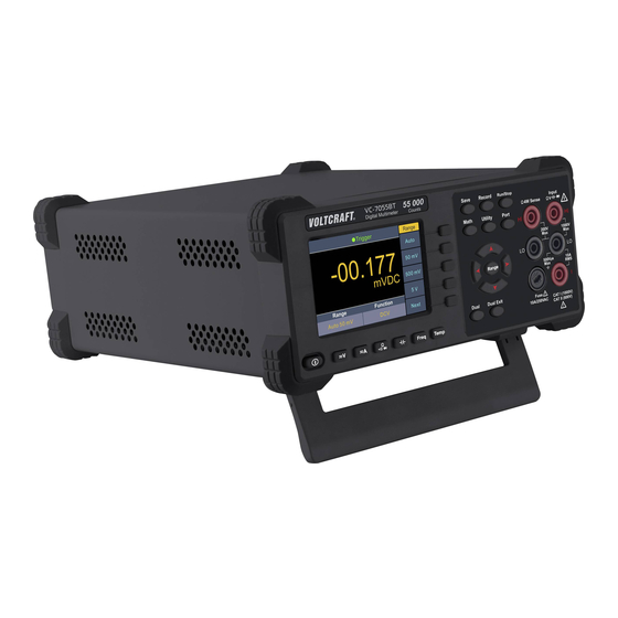
2.Quick Start Foot Stool Adjustment Unfold the foot stool on the bottom of the multimeter. Front Panel Overview Figure 2- 1 Front panel overview Item Name Description Display the user interface Menu selection Activate the corresponding menu Keys Operation Keys Save Collect data in manual record. - Page 10 2.Quick Start Run/Stop Start or stop auto trigger. When the trigger is stopped, the displayed data will be held. Math Perform math operations (Max/Min, dB/dBm) on the measurement results. Utility Set the auxiliary system function, including Language, Backlight, Clock, Default. Port Set Serial port.
-
Page 11: Rear Panel Overview
2.Quick Start Dual Exit Press the key to exit dual display mode. Rear Panel Overview Figure 2- 2 Rear panel overview Item Name Description RS232 Connect the PC through this port. Line Fuse The fuse rating is . To replace the fuse, see page 250 V, F1AL 38, Appendix C: Line Fuse Replacement. -
Page 12: Power On
2.Quick Start Trigger Mode Status Icon Display Description Icon Description Trigger Auto trigger Auto record function is running Manual record Figure 2- 3 User interface (Single display) Figure 2- 4 User interface (Dual display) Power On (1) Connect the instrument to the AC supply using the supplied power cord. Warning: To avoid electric shock, the instrument must be grounded properly. -
Page 13: Measurement Connections
2.Quick Start Measurement Connections After selecting the desired measurement function, please connect the signal (device) under test to the multimeter according to the method below. To avoid instrument damage, do not discretionarily switch the measurement function when measuring. DC Voltage Measurement AC Voltage Measurement DC Current Measurement AC Current Measurement... - Page 14 2.Quick Start Capacitance Measurement Frequency/Period Measurement Temperature Measurement...
-
Page 15: Functions And Operations
3.Functions and Operations 3. Functions and Operations To Set The Range The instrument provides auto and manual range. In auto range, the multimeter selects a proper range automatically according to the input signal; in manual range, you can use the front panel key or menu softkey to set the range. The auto range can bring a lot of convenience for users while the manual range provides higher reading precision. -
Page 16: Measurement Speed
3.Functions and Operations Measurement Speed The instrument provides three types of measurement speed: "Low" speed is 4 reading/s; "Mid" speed is 16 reading/s; "High" speed is 65 reading/s. In DCV, ACV, DCI, ACI and 2-wire / 4-wire resistance measurements, the measurement speed is selectable. -
Page 17: Measuring Ac Voltage
3.Functions and Operations Press the Rel softkey to turn on or off the relative operation. For relative operation, the multimeter subtracts the pre-specified value of REL operation from the actual measurement result and displays the result. See page 25, Relative Value. Measuring AC Voltage This section describes how to configure AC voltage measurements. -
Page 18: Measuring Dc Current
3.Functions and Operations Measuring DC Current This section describes how to configure DC current measurements. Operating Steps: 1. Enable the DCI measurement. Press on the front panel to enter DCI measurement mode. 2. Connect the test lead. 3. Set the range. Press the Range softkey to set the range. -
Page 19: Measuring Resistance
3.Functions and Operations Press on the front panel, press it again to enter ACI measurement mode. 2. Connect the test lead. 3. Set the range. Press the Range softkey to set the range. Auto range automatically selects the range for the measurement based on the input. Note: The multimeter uses two kinds of fuses for current protection: the 10 A current ... - Page 20 3.Functions and Operations Press on the front panel to enter resistance measurement mode. Press the Model softkey to switch between Ω2W and Ω4W. (2-wire Resistance) (4-wire Resistance) 2. Connect the test lead. 3. Set the range. Press the Range softkey to set the range. Auto range automatically selects the range for the measurement based on the input.
-
Page 21: Continuity Test
3.Functions and Operations 10% over range for all ranges except 50 MΩ range. If the reading exceeds 55 MΩ in 50 MΩ range, "overload" will be displayed. 4. Set the measurement speed. Press the Speed softkey to switch between Low, Mid or High. See page 13, Measurement Speed . -
Page 22: Diode Test
3.Functions and Operations Press the Threshold softkey to set the short-circuit resistance. Press to move the cursor, press to increase or decrease the value.The range for the 0 Ω to 1000 Ω. The default is 50 Ω. 5. Continuity measurements behave as follows: Circuit resistance to be measured Display and beep Displays measured resistance and beeps (if... -
Page 23: Measuring Capacitance
3.Functions and Operations > 3 V Displays "Open" with no beep Measuring Capacitance This section describes how to configure capacitance measurements. Operating Steps: 1. Enable the capacitance measurement. Press on the front panel to enter capacitance measurement mode. 2. Connect the test lead. Tip: Please short contact the two feet of an electrolytic capacitor by using a test lead before measuring the electrolytic capacitor. -
Page 24: Measuring Temperature
3.Functions and Operations to measure the frequency or period directly. This section describes how to configure frequency and period measurements. Operating Steps: 1. Enable the frequency/period measurement. Press on the front, in the right menu, press the model soft key to switch and select Freq/Period measurement 2. - Page 25 3.Functions and Operations measurements require a temperature transducer probe. The supported probes are type ITS-90 K type and PT100 sensor. Operating Steps: 1. Enable the temperature measurement. Press on the front panel to enter temperature measurement mode. 2. Connect the test lead. 3.
-
Page 26: Dual Display
3.Functions and Operations Dual Display Using dual display function, you can view the readings of two measurement functions simultaneously. Figure 3- 1 Dual Display Operating Steps: 1. Press one of the measurement function keys to turn on the primary measurement function. -
Page 27: Data Hold
3.Functions and Operations reading. Data Hold Data hold keeps the current reading on the display. (1) Press the Run/Stop panel key to Stop the trigger, and the current reading is kept on the display screen. (2) Press the Run/Stop key again to continue triggering. Math The multimeter provides these math functions: Max/Min, dB/dBm and relative. -
Page 28: Relative Value
3.Functions and Operations Press the Ref R softkey to select the reference resistance. The value may be 50 (default), 75, 93, 110, 124, 125, 135, 150, 250, 300, 500, 600, 800, 900, 1000, 1200, or 8000 Ω. dB Function dB represents the relative value which is used in the relative operation of dBm value. -
Page 29: Data Record Function
3.Functions and Operations Data Record Function Data record function includes manual record and auto record. You can use any or both functions to record the data. Manual and automatic records share a table of data stored in internal storage.The maximum number of recorded points is 1000.After collecting the data, it can be exported to the computer. - Page 30 3.Functions and Operations 15 ms to 9999.999 s. 2. Record data: Press the Start softkey to start auto record. The icon will show up on the top of the display. Press the Stop softkey to stop recording, the data table shows the readings taken.
-
Page 31: Port Configuration
3.Functions and Operations Port Configuration You can configure the port parameters in port configuration. Serial Press the front panel key, press the Serial softkey to access the serial port setting menu. Press the Baud softkey to select the desired baud rate from 2400, 4800, 9600, 19200, 38400, 57600 or 115200. - Page 32 3.Functions and Operations Type Item Value Baud 115200 Data bits Port Odd-Even None Stop bit Utility BLight 100% dB/dBm Off/On Function Math Rel R 50Ω Db Rel 0Ω Max/Min Static Auto Clear Manual Clear Record Point Interval Aoto On/Off Run/Stop Beeper Threshold 50Ω...
-
Page 33: Measurement Tutorial
4.Measurement Tutorial 4. Measurement Tutorial Loading Errors (DC Voltage) Measurement loading errors occur when the resistance of the DUT(Device-Under-Test) is an appreciable percentage of the multimeter's input resistance, as shown below. = ideal DUT voltage = DUT source resistance = multimeter input resistance 100 R ... -
Page 34: True Rms Ac Measurements
4.Measurement Tutorial True RMS AC Measurements The AC measurement of the multimeter has true RMS response. Power dissipated in a resistor is proportional to the square of an applied voltage, independent of the wave shape of the signal. This multimeter accurately measures true rms voltage or current, as long as the wave shape contains negligible energy above the meter’s effective bandwidth. -
Page 35: Loading Errors (Ac Voltage)
4.Measurement Tutorial Loading Errors (AC Voltage) In the AC voltage function, the input impedance of the multimeter appears as a 1 MΩ resistance in parallel with 100 pF of capacitance. The cabling that you use to connect signals to the multimeter also adds capacitance and loading. The table below shows the multimeter's approximate input resistance at various frequencies. -
Page 36: Crest Factor Errors (Non-Sinusoidal Inputs)
4.Measurement Tutorial Crest Factor Errors (non-sinusoidal inputs) A common misconception is that because an AC multimeter is true RMS, its sine wave accuracy specifications apply to all waveforms. Actually, the shape of the input signal dramatically affects measurement accuracy. A common way to describe signal wave shapes is “crest factor”. -
Page 37: Troubleshooting
5.Troubleshooting 5. Troubleshooting 1. The instrument is powered on but no Display. 1) Check if the power is connected properly. 2) Check if the line fuse which is below the AC Mains Input is used appropriately and in good condition (see page 38, Appendix C: Line Fuse Replacement). 3) Restart the instrument after the steps above. -
Page 38: Technical Specifications
6.Technical Specifications 6. Technical Specifications Function Range Resolution Accuracy: ± (% of reading + LSB) 50.000 mV 0.001 mV 0.1% + 10 500.00 mV 0.01 mV 0.025% + 5 5.0000 V 0.0001 V 0.025% + 5 DC Voltage 50.000 V 0.001 V 0.03% + 5 500.00 V... - Page 39 6.Technical Specifications [1] Specifications are for 30-minute warm-up, "Low" measurement rate and calibration temperature 18℃ - 28℃. [2] 10% over range on all ranges, except 1,000 V DCV, 750 ACV, 10 A DCI, 10 A ACI, 50 MΩ resistance, and 50 mF capacitance.
-
Page 40: Appendix
7.Appendix 7. Appendix Appendix A: Enclosure Standard Accessories (subject to final delivery): Spare Fuse Crocodile clip Test lead Power Cord Quick Guide CD Rom Safety hintsheet Appendix B: General Care and Cleaning General Care Do not store or leave the instrument where the liquid crystal display will be exposed to direct sunlight for long periods of time. -
Page 41: Appendix C: Line Fuse Replacement
7.Appendix Appendix C: Line Fuse Replacement The line fuse is in the plastic fuse box below the power line input on the rear panel. Warning: Disconnect the line cord at the rear panel and remove all test leads connected to the instrument before replacing the line fuse. Failure to do so could expose the operator to hazardous voltages that could result in personal injury or death.
Need help?
Do you have a question about the VC-7055BT and is the answer not in the manual?
Questions and answers