Table of Contents
Advertisement
Quick Links
Advertisement
Table of Contents

Subscribe to Our Youtube Channel
Related Manuals for VOLTCRAFT 2203066


Summary of Contents for VOLTCRAFT 2203066
- Page 1 VC-7055BT Digital Multimeter Quick Guide...
-
Page 2: Table Of Contents
Table of Contents 1.Safety Information ...................... 1 Safety Terms and Symbols ..................... 1 General Safety Requirements ....................2 Measurement Limits ......................3 Main Input Terminals (HI Input and LO Input) Measurement Limits ............3 Current Input Terminal (I) Measurement Limits ..................3 Sense Terminals (HI Sense and LO Sense) Measurement Limits .............. -
Page 3: Safety Information
1.Safety Information 1. Safety Information Safety Terms and Symbols Safety Terms Terms in this Manual. The following terms may appear in this manual: Warning: Warning indicates the conditions or practices that could result in injury or loss of life. Caution: Caution indicates the conditions or practices that could result in damage to this product or other property. -
Page 4: General Safety Requirements
1.Safety Information General Safety Requirements Before any operations, please read the following safety precautions to avoid any possible bodily injury and prevent this product or any other products connected from damage. In order to avoid any contingent danger, this product is only used within the range specified. -
Page 5: Measurement Limits
1.Safety Information Measurement Limits The protection circuitry of the multimeter can prevent damage to the instrument and protect against the danger of electric shock, when the Measurement Limits are not exceeded. To ensure safe operation of the instrument, do not exceed the Measurement Limits shown on the front panel, it is defined as follows: The user-replaceable 10 A current-protection fuse is on the front panel. -
Page 6: Sense Terminals (Hi Sense And Lo Sense) Measurement Limits
1.Safety Information same voltage as the LO Input terminal, unless a current protection fuse is open. Sense Terminals (HI Sense and LO Sense) Measurement Limits The HI and LO sense terminals are used for four-wire resistance measurements. The Measurement Limit from HI Sense to LO Input is 200 Vpk. The Measurement Limit from HI Sense to LO Sense is 200 Vpk. -
Page 7: Quick Start
2.Quick Start 2. Quick Start General Inspection After you get a new multimeter, it is recommended that you should make a check on the instrument according to the following steps: 1. Check whether there is any damage caused by transportation. If it is found that the packaging carton or the foamed plastic protection cushion has suffered serious damage, do not throw it away first till the complete device and its accessories succeed in the electrical and mechanical property tests. -
Page 8: Foot Stool Adjustment
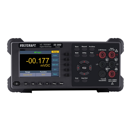
2.Quick Start 295 mm Foot Stool Adjustment Unfold the foot stool on the bottom of the multimeter. Front Panel Overview Figure 2-1 Front panel overview Item Name Description Display the user interface Menu selection Activate the corresponding menu Keys Operation Keys Save Collect data in manual record. - Page 9 2.Quick Start Record Access menus of manual record and auto record. See page 11, Data Record Function. Run/Stop Start or stop auto trigger. When the trigger is stopped, the displayed data will be held. Math Perform math operations (Max/Min, dB/dBm) on the measurement results.
-
Page 10: Rear Panel Overview
2.Quick Start Measurement DC or AC voltage measurements Function Keys DC or AC current measurements Resistance, continuity, and diode measurements Capacitance measurements Frequency/Period measurements Temperature measurements Dual Press this key to display the function list on the right menu, select a function, if the function is supported, the reading will be displayed in the Vice Display. -
Page 11: User Interface
2.Quick Start User Interface Trigger Mode Status Icon Reading Operation Menus Unit Range Function Trigger Mode Status Icon Display Description Icon Description Trigger Auto trigger Auto record function is running Manual record Figure 2-3 User interface Primary function reading Secondary function Primary function Figure 2-4 User interface (Dual display) Power On... -
Page 12: Measurement Connections
2.Quick Start Measurement Connections After selecting the desired measurement function, please connect the signal (device) under test to the multimeter according to the method below. To avoid instrument damage, do not discretionarily switch the measurement function when measuring. DC Voltage Measurement AC Voltage Measurement DC Voltage AC Voltage... -
Page 13: Data Record Function
2.Quick Start Capacitance Measurement Frequency/Period Measurement Capacitance AC Signal Temperature Measurement Temp Transducer Data Record Function Data record function includes manual record and auto record. You can use any or both functions to record the data. The readings recorded in manual record or auto record will be saved into a same data table in the internal memory. -
Page 14: Auto Record
2.Quick Start shown, you can still save current reading by pressing the key.) Note: When the recording data exceeds the current range, the data will be marked as "overload". When the relative operation is turned on, the recorded data will still be the original ... -
Page 15: Troubleshooting
2.Quick Start will last about a few hundred milliseconds, and the data acquired in this period will be marked as "invalid". When the dual display is enabled, only the reading of main display function can be saved. Troubleshooting 1. The instrument is powered on but no Display. 1) Check if the power is connected properly. -
Page 16: Appendix
3.Appendix 3. Appendix Appendix A: Enclosure Standard Accessories (subject to final delivery): Power Cord Quick Guide Spare Fuses Test Leads Crocodile Clips Safety Hintsheet Software CD Appendix B: General Care and Cleaning General Care Do not store or leave the instrument where the liquid crystal display will be exposed to direct sunlight for long periods of time. -
Page 17: Appendix C: Line Fuse Replacement
3.Appendix Appendix C: Line Fuse Replacement The line fuse is in the plastic fuse box below the power line input on the rear panel. Warning: Disconnect the line cord at the rear panel and remove all test leads connected to the instrument before replacing the line fuse. Failure to do so could expose the operator to hazardous voltages that could result in personal injury or death.
Need help?
Do you have a question about the 2203066 and is the answer not in the manual?
Questions and answers