
Related Manuals for Kondo KXR-L6


Summary of Contents for Kondo KXR-L6
- Page 1 Six Legs Type KXR-L6 Assembly Manual Support Information www.kondo-robot.com KONDO KAGAKU Co., Ltd. Service Dept. support@kondo-robot.com © 2017 Kondo Kagaku Co., Ltd. Ver.1.0...
-
Page 2: Table Of Contents
Table of Contents ■ Safety Precautions ■ Preface ■ Prior to Assembly ●List of Parts Used ●Accessories ●Servo Motors ●Screw Handling ●Frame Parts ●Servo ID and Position ■ Robot Assembly ●Full Robot Assembly Procedures ●Servo ID Setting ●Body Assembly ●Leg Assembly ●Attaching All Parts ... -
Page 3: Safety Precautions
Safety Precautions Due to the nature of this product as an assembly kit, consequences, damage, or injury resulting from the use of this product are the user's responsibility. Please use this product with that in mind. In order to prevent danger to the user and others, as well as property damages, the safety precautions listed below must be followed. -
Page 4: Preface
Preface Thank you for purchasing the KXR robot assembly kit. The KXR system enables you to create various robots by combining frame parts with servo motors as a part of the structure. The basic format is provided as a set, and sample motions are also included, so you can confirm the robot's operations as soon as it is assembled. -
Page 5: Prior To Assembly
Prior to Assembly List of Parts Used (1) KXR-L6 ■ Servo First, Setting Servo IDs. Example of ID sticker application No. 03115 No. 03116 (6pcs) KRS-3301 ICS No. 03103 No. 03104 (6pcs) No. 03105 (18pcs) KRS-3304 ICS ■ Frame Parts x 8 x 5 No. 02305 No. 02306 Joint Frame Arm supporter 3300A 3300A No. 02300 No. 02301 Joint Base Joint Nut x 3 x 3 No. 02305 No. 02305 No. 02314 Joint Frame... - Page 6 Prior to Assembly List of Parts Used (2) KXR-L6 ■ Frame Parts x 4 x 4 x 5 No. 02309 No. 02309 Dummy Servo Dummy Servo No. 02311 No. 02157 -Upper -Bottom Lock Ring Cap Small Diameter No. 02311 Horn B Body Panel x 4 x 4 x 6 x 2 No. 02308 No. 02308 No. 02159 No. 02313 Angle Angle No. 02311 Small Diameter Panel Spacer Lock Ring...
- Page 7 Prior to Assembly List of Parts Used (3) KXR-L6 ■ Frame Parts x 5 x 1 x 4 x 4 No.02315 No.02315 No.02315 Supporter B Supporter B Arm supporter Spacer 2 Spacer 3300B No. 02318 No. 02318 Gripper A-a Gripper A-b x 5 x 1 x 2 No. 02318 No. 02319 No.02316 No.02317 Sensor Base A Gripper A Flat Frame Bottom Spacer Spacer/Bush (for Option)...
- Page 8 Prior to Assembly List of Parts Used (4) KXR-L6 ■ Cable / Screw *The number of parts used is the maximum number used for each assembly example. x 6 Length =60mm No. 02329 Length =100mm Length =120mm No. 02330 No. 02166 No. 02177 LV Power Source ZH Conversion Cable Length =160mm No. 02331 Switch Harness x 4 Length =200mm No. 02332...
-
Page 9: Accessories
Prior to Assembly Accessories KRS-3300 Series Servo Servo motors are integrated with gears for raising the output torque and a control board that enables stopping at any angle. Using servo motors in the robot’s joints makes it easy to send angle commands to the joints and enables multiple motors to be accurately controlled at the same time. - Page 10 Prior to Assembly Accessories Battery / Charger *The included battery and charger differ with the set. Do not use the included USB charger (BX-31LF/BX-32MH) from the USB port of a computer. When charging use a commercially available AC adaptor (1-2A) that supports USB. Make sure to charge the battery before assembly and before operation.
-
Page 11: Servo Motors
Prior to Assembly Servo Motor Part Name of Servo Motor (KRS-3300 Series) Upper Side Frame part installation hole This kit uses M2 screws. Upper Case Upper Axis (Final Axis) Middle Case Bottom Case Serration Groove surrounding the shaft. ZH connector Whichever it is connected to, there is no impact on operations. Origin The top of the shaft has a concave origin; find this position and install the part. M3 Screw Hole This kit uses M3 screws. Align the protruding position and firmly insert all the way in. Be careful not to push it in backward. Bottom Side Case Screw Bottom Axis (Free Axis) 2.6 Tapping Screw Hole This kit uses 2.6 - 4 screws. The light comes on when the power is on. KRS-3301 ICS : Red KRS-3304 ICS : Blue Frame parts are labeled Upper Side and Bottom Side to indicate the installation direction. -
Page 12: Screw Handling
Prior to Assembly Screw Handling Always use a screwdriver that is right for the screw head. With this kit, use a #0 screwdriver for M2 screws and #1 screwdriver for M2.6 and larger screws. “M"refers to millimeter-scale screw thread. Matching metal nuts can be used. Tighten screws that Tightening screws With multiple screws are diagonally aligned Right Right ① ③ Tighten while ④ applying pressure ② Tighten Tighten lightly further (Example or tightening order) When using several screws to Further, when using more than Tighten the screw in a vertical secure parts, first tighten each four screws to secure parts avoid position while applying pressure screw lightly, and then tighten adding uneven pressure to the on the screw head with the them further to secure the parts parts by alternately tightening screwdriver. evenly with equal force. screws that are diagonally aligned. If you strip the screw head, remove the screw without applying too much force and ... -
Page 13: Frame Parts
Prior to Assembly Basic Frame Parts ■ Joint Base Joint parts for connecting the arms and frame, etc. with the servos. Put on the plastic joint nut and screw to secure. Plastic joint nuts can be replaced with M2/M2.6 metal nuts. Front Side (Horn Side) Back Side (Nuts Side) Make sure the installation direction is correct. Joint nut screw hole How to set Joint Nuts ①Bend the M2.6 end. ②Fit into the joint base. M2.6 Double Joint Base (When installing joint bases) Cut the M2 end. M2-8 x 4 Put the top sides together facing each other. (The nut side faces out) - Page 14 Prior to Assembly Basic Frame Parts ■ Arm This part supports and rotates the servo with two shafts. The upper shaft and bottom shaft are used as a pair. Make sure the position of installation bearings and the length of the arms are correct. Arm-38 Upper Bottom Arm-26 Arm-20 38mm Upper Bottom Upper Bottom 26mm 20mm (Back) Serration Free Serration Free Serration Free Caution: Cross upper arm-28 is exclusively with the cross upper frame. Example:Cross Frame Bottom Upper Free Serration Serration faces the top side. There are no screw holes for guiding cables.
-
Page 15: Servo Id And Position
Prior to Assembly Servo ID and Position KXR-L6 Connect servo to servo and servo to RCB-4mini using ZH-ZH connection cable. RCB-4mini s SIO ports (servo connectors) are divided into two systems, SIO1-3 and SIO5-7. Within the same system, changing the port does not impact operations, but be aware that if the system is incorrect, the robot won t function properly. Servo ID stickers are classified with the symbols ◯ and □. *Always connect ID 0 to the SIO5-7 system. The explanations in this manual use the following wiring layout. SIO 1〜3 SIO 5〜7 160mm 160mm SIO 5 SIO 1 160mm 160mm SIO 6 SIO 2 120mm 120mm 160mm 160mm SIO 7 SIO 3 KRS- KRS- 3304 ICS 3304 ICS 120mm 120mm KRS- KRS- 3304 ICS... -
Page 16: Robot Assembly
Full Body Assembly Procedures KXR-L6 Procedure 0 Setting Servo IDs Procedure 1 Body Assembly Procedure 2 Leg Assembly 1 Leg assembly Multiuse parts 1 BT(Battery) Box 2 Joining Procedure 3 Full Assembly 1 Legs 2 Electronic compnents KXR-L6 *Reference diagram... -
Page 17: Servo Id Setting
Setting Servo IDs 1 KXR-L6 ■ Setting Servo IDs KRS-3301 First, apply ID stickers to the servos. KRS-3304 Example of ID sticker application ● KO Driver Installation 1. Set the Dual USB adapter HS switch to ICS mode, connect the Serial Extension Cable, and then plug it into the USB port of your personal computer. When connected to the LED: RED USB port in ICS mode, the Dual USB ICS MODE Adapter HS LED lights up red. 2. When connected to the Windows PC Dual USB Adapter HS for the first time, the Add New Hardware Wizard will automatically run. Complete the setup following 1.5m Serial Extension Cable the KO Driver Installation Manual in the USB folder in the included CD-ROM. ● Dual USB Adapter HS COM Confirmation ... - Page 18 Setting Servo IDs 2 KXR-L6 ● Changing Servo ID Settings 1. Copy the Serial Manager folder on the CD-ROM included with the set onto the PC desktop. 2. Double-click ICS3.5Manager.exe in the copied Serial Manager folder and launch ICS3.5Serial Manager. ICS3.5Serial Manager allows you to change settings f o r I C S 3 . 5 / 3 . 6 - s p e c . s e r v o I D s , ...
- Page 19 Setting Servo IDs 3 KXR-L6 5. Select the set ID number from the ID pull-down menu. 6. Press the Write button on the ID menu and write the ID onto the servo. If successful, ID: Write Complete will be displayed in the lower-left box. If it fails, Communication Failed will be displayed, so confirm the procedures and press the Write button again. In particular, be sure that Dual USB Adap- tor HS is in Serial Mode. 7. Just to be sure, confirm the ID. When you press the Acquire button, the ...
-
Page 20: Body Assembly 1
Body Assembly 1 Multiuse Parts KXR-L6 ■Assemble all the multiuse parts. Parts used ◯Joint base x18 ◯Joint nut x18 (First assemble 18 sets.) ①Attach Joint nut to Joint base. Joint base A: 12 Joint nut screw holes 1. 2. M2部 M2.6部 Joint base B: 6 1.Cut 2 M2 parts. - Page 21 Body Assembly 1 (battery) KXR-L6 ■Assemble by wiring through the BT(Battery) box. Parts used Assemble part Assembly parts completed ◯BT Box plate x2 ◯M2 ー 6 x8 BT Box ◯BT Side plate x2 ◯ZH connection cable 2 ◯BT Hatch x2 160mm x6 ◯Decale ① Wire six ZH connection cables of 160 mm to the BT box plate. ①-1. ①-2. Pull the cable to the length indicated below. M2 ー 6 BT Box plate ①-3. Wire the cable with the hook gap in a vertical position and store under the hook. BT Side plate x2 *Make sure the direction of the BT side plate is correct.
- Page 22 Body Assembly 1 (battery) KXR-L6 ①-4. ①-5. Apply the decal to the cable. Secure with tape, etc. so it doesn't come out easily. *Firmly apply the tape aligned with the uneven surface. Right legs Left legs Right Left Front Front Right Left Center Center *As seen upside down Right Left (The diagram is only of the BT box plate Rear Rear so that it is easy to view.) ② Attach the plate on the opposite side so that it sandwiches the two BT hatch plates. BT Box BT Hatch x2 M2 ー 6 BT Box plate Hinge positions *If installation proves difficult, try temporarily securing the BT box plate and inserting one BT hatch at a time.
- Page 23 Body Assembly 2 Joining KXR-L6 ■Assemble the body parts. Parts used Assemble part Assembly parts completed Body ◯Servo(ID 1) (ID 4)(ID 7) x2 ◯M2 ー 6 x2 ◯M2 ー 8 x12 ◯Body panel x4 ◯M2 ー 12 x12 ◯Lock ring x1 ◯M2.6 ー 10 x2 ◯Lock ring cap x1 ◯Backpack cover x1 ◯Backpack base x1 ◯Joint nut x1 ◯Joint base B x6(Assembled) ① ①-1. ①-2. Assenble 2 sets M2 ー 12 M2 ー 8 Body panel...
- Page 24 Body Assembly 2 Joining KXR-L6 ② ②-1. ②-2. Rotate until it clicks into place. *Assemble by wiring M2 ー 6 through the BT Leg pate. Rear Backpack base Rear Front Front About the lock portion for the BT box and body parts ①Align the notch and protrusion, and attach. ②Rotate until it clicks into place. ●BT Box side ●Body part top side Lock ●Leg plate ●Lock ring ●Back pack ②-3. Connect the cable. Connect all six. Rear Left leg side Right leg side 160mm Front 160mm Whichever connector is used, it has no effect on operations, but be sure the cable does not overlap or get pinched.
- Page 25 Body Assembly 2 Joining KXR-L6 ②-4. ②-5. M2.6 ー 10 Use the M2.6 part of joint nuts cut when making the neck. The screw side (facing out) is the side with bevelling around the holes. M2.6 Nut Backpack cover ③ ④ Rotate until it clicks into place. Detach case screw Lock ring Lock ring cap Case screw Body panel Front Rear ⑤ Attach case screws. Body Case screw Rear Front Front Rear...
-
Page 26: Leg Assembly
Leg Assembly KXR-L6 ■Assemble legs. Parts used Assemble part Assembly parts completed ◯Servo(ID2)(ID3)(ID5)(ID6) ◯M2 ー 6 x24 ◯M2.6 ー 10 x36 (ID8)(ID9) x2 ◯M3 ー 6 x12 ◯Bottom arm 3300-20 x6 ◯2.6 ー 4 x12 ◯Upper arm 3300-26 x6 ◯Bottom arm 3300-26 x6 ◯Upper arm 3300-38 x9 ◯Bottom arm 3300-38 x9 ◯Flat frame x12 ◯Joint base A x12(Assembled) Assemble the six leg sets. ① Detach case screws. Use servos in the combination indicated below. Create pairs for each leg so that 〜 the IDs don't mix. Case screw 〜 ②... - Page 27 Leg Assembly KXR-L6 ③ Joint base A (ID 2/5/8) upper arm 3300-26 (ID 2/5/8) M2.6 ー 10 M3 ー 6 *Confirm the servo origin and attach it straight. (ID 3/6/9) ④ ⑤ M2.6 ー 10 (ID 2/5/8) M2.6 ー 10 *No connecter side Bottom arm 3300-26 (ID 3/6/9) 2.6 ー 4 (ID 3/6/9) (ID 2/5/8) Bottom arm 3300-20 ⑥ Joint base A Upper arm...
- Page 28 Leg Assembly KXR-L6 ⑦ ⑧ *Either upper or bottom can be used. Bottom arm (ID 3/6/9) 3300-38 M2.6 ー 10 (ID 2/5/8) Upper/Bottom arm 3300-38 *No connecter side 2.6 ー 4 M2.6 ー 10 (ID 3/6/9) (ID 2/5/8) ⑨ (ID 3/6/9) (ID 3/6/9) (ID 2/5/8) (ID 2/5/8) 120mm *Whichever connector is used, *Assemble the six leg sets. it has no effect on operations, but be sure the cable does not overlap or get pinched.
-
Page 29: Attaching All Parts
Parts Combination 1 Legs KXR-L6 ■Attach the legs. Parts used Assemble part Assembly parts completed Parts combination ◯Upper arm 3300-20 x6 ◯M2 ー 6 x6 ◯Cable guide X x6 ◯M2.6 ー 10 x6 ◯M3 ー 6 x6 ◯Body x1(Assembled) ◯2.6 ー 4 x6 ◯Leg x6(Assembled) ◯ZH Connection cable 2 120mm x6 ① Attach the upper arm to the body servo. Legs Layout Uper arm 3300-20 x6 Left Right M3 ー 6 Legs Legs *Confirm the servo origin ... - Page 30 Parts Combination 2 Backpack KXR-L6 ■Attach the electronic components to the backpack and connect. Parts used Assemble part Assembly parts completed Backpack ◯RCB-4mini x1 ◯M2 ー 6 x4 ◯LV Power Source Switch Harness x1 ◯2.6 ー 4 x6 ◯ZH Connection cable x1 Confirm the electronic components for mounting. These three points are common to the KXR series. RCB-4mini ZH Conversion Cable Conversion cable for connecting serial extension The control board for transferring motion cable connected with the PC and the RCB-4mini's data from the PC and moving the robot. COM port. Servo connecter ZH type-3PIN x12 To Serial Extension Cable(PC) To Servo etc. ZH type-3PIN To COM port LV Power Source Switch Harness VH type-2PIN The white circle side is power To RCB-4mini ON. The power is normally OFF unless the robot is being operated.
- Page 31 Parts Combination 2 Backpack KXR-L6 ①Attach the electronic components. ①-1. Attach RCB-4mini M2 ー 6 COM port *When inserting the connector, make sure the direction is correct. 2.6 ー 4 2.6 ー 4 To RCB-4mini Attach so that the white wire comes up. To COM port To Battery box at RCB-4mini ①-2. Attach ZH Conversion cable ①-3. Attach LV Power Source Switch Harness...
- Page 32 Parts Combination 2 Backpack KXR-L6 ②Connect wire. White: SIO port Green: AD port Servo/receiver, etc. Sensor, etc. Right 160mm Left 160mm Rear Rear SIO3 SIO7 Right Left 160mm 160mm Center Center SIO2 SIO6 SIO1 SIO5 Left Right 160mm 160mm Front Front Power Blue : COM port LV Power Source Switch Harness ZH Conversion cable (PC)...
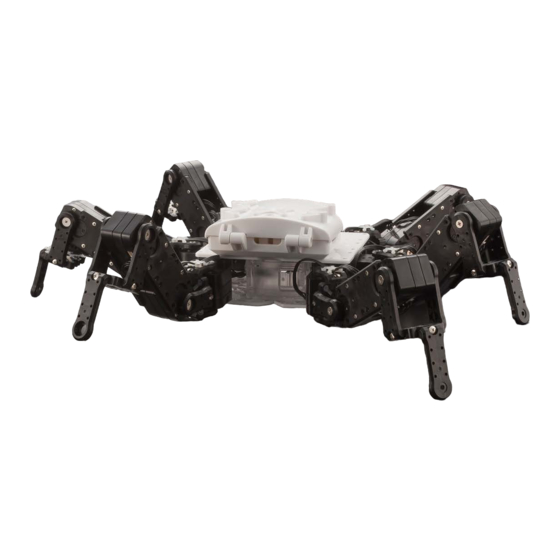
- Page 33 Complete KXR-L6 Assembly completed ! The following will explain how to mount the battery and run motions.
-
Page 34: Robot Operations
Battery Mounting ■Mount the battery. Before installation, check to be sure the power switch is OFF. Do not turn the power switch ON until connecting to the PC. Always read through the battery and charger manuals before use. Also, if using an LiFe battery, to prevent damage from over discharge, be sure to read about Motion when voltage reduced (voltage check function on HTH4) after the instructions for running motions. ①-1.Push down lightly on the hatch clasp and slide it. ②Put in the battery in the direction of the photo so the connector goes in first. ①-2.Once unlocked, the hatch opens on both sides. *Do not force the battery in. Check to see if it s catching on a cable. ③Connect the connector. ④Close both sides of the hatch to complete the process. *Be sure the polarity is correct. Connect cables of the same color so that the clasps join. ※Reference photo: KXR-L4... -
Page 35: Connecting With Pc
■ Run the sample motion Enable the low voltage motion setting to prevent over discharge, and run the motion. ■ Set the Dual USB adapter HS switch to Serial mode KO Driver is driver software that enables Windows OS to recognize Kondo Kagaku s USB adaptor. This allows the servos and robot to communicate with the PC via a USB connection. 1. Set the Dual USB adapter HS switch to Serial mode, connect the Black-and-White Extension Cable, and then plug it into theUSB port of your personal computer.When connected to the USB port in ICS mode, the Dual USB Adapter HS LED lights Green. - Page 36 Connection with PC 2 ■ Install HeartToHeart4 Software HTH4 (HeartToHeart4) is used to adjust the robot. The software is exclusively for RCB-4HV/RCB-4mini (referred to as “RCB-4” below) and has been designed to make it easy for anyone to control the robot. Using this software allows you to make full use of the functions needed to freely operate the robot, including the neutral position check (checks that parts have been assembled correctly with the servos in the origin (neutral) position), basic positioning adjustment (trim adjustment), motion creation, sensor settings, etc.
- Page 37 Connection with PC 3 4. Copy Sample Data Copy the “Sample_Projects_KXR(Vxx.x)" in the HeartToHeart4 folder on the CD-ROM to a con- venient location on your personal computer. In the example, it is copied to the desktop. *The version number differs depending on the kit and included CD-ROM. 5. Activate KXR Turn the KXR power switch ON. [IMPORTANT] • Check the RCB-4 wiring and each servo motor once again be- foreturning the power ON.
-
Page 38: Trim Confirmation
Trim Position: ● The pose where only the trim is adjusted from the Neutral Position. This becomes the robot's basic posture. It is the upright standing posture for KXR-L6, and is used when adjusting trim. ● Home Position: The first and last position when motions are run. When the motion is completed, ... - Page 39 3. Select the “Hello_KXR(Vxx.x)" project in the Sample_projects (Vxx.x) folder that was copied onto the computer above. Hello̲KXR-L6(Vxx.x) 4. When the project is imported, the new proj- ect name in the New Project window be- comes the same as the name of the folder that was imported.
- Page 40 Trim Adjustment 3 6. Press the “Project Setting Window" but- ton.The Project Setting window opens when selected. 7. Set the COM communication rate and ICS communication rate to 115200 . Read the cautions on the next page before pressing the RAM button. 8. Keep clicking on "RAM" button, al- lowing 2 to 3 seconds between each click until the robot slowly moves to trim position. This applies when you run the robot for the first time. When the servos are shipped from the factory, there is no data loaded into them, thus the "RAM" button needs to be clicked multiple times for initiali- sation. Once initialised, pressing "RAM" once will be enough to get robot moving. ...
- Page 41 Confirm Trim Position The correct trim position is the pose shown in the diagram below. Press the RAM button and confirm that the robot assumes this pose. When the RAM button is clicked, the robot will assume this posture. If the robot does not match this pose, then the origin setting is wrong. Retrace the origin setting steps to determine and correct the part that is off track. Proceeding to set the Home Position without confirming this posture can cause damage to the servo motors.
- Page 42 Trim Adjustment 4 9. Click the "Trim Adjustment" tab at the top of the Project Setting window, to change screens. 10. Press the "Sync" button in the toolbar of the Main Window. If the color of the button changes after pressing, it is turned ON. In the Sync state, the corresponding servo motor operates on a real-time basis by moving the HeartToHeart4 slide bar. *The screen layout is an example for reference purposes. 11. Adjust areas where the trim is out of alignment with reference to the image. The trim position is an important base position for executing motions. In particular, if the left and right legs are not in perfect alignment, walking, etc. in the sample motion will not pro- ceed smoothly. When the trim is out of alignment, the overall motion will also be off, so ...
- Page 43 Trim Adjustment Points Trim Adjustment Points Adjust one side completely and then use that as the standard when adjusting the opposite side. Align the leg servos so that when looked at from the side their output shafts are lined up in a straight line. ...
- Page 44 Trim Adjustment 5 12. When all the Trim Adjustments are complet- ed, press the "Save All to ROM" button in the Project Setting window. 13. The “Set Initial Posture at Start-up" dialog appears. Select the “Trim Position". Writing of the data to RCB-4 begins.
-
Page 45: Running Sample Motions 1
Running Sample Motions 1 ■ Running Sample Motions This will run the sample motions for KXR. If the robot keeps falling or does not move properly, try trimming the servos again. The following uses "Hello̲KXR-L6(Vxx.x)" as an example. Please refer to "Trim Adjustment" section if necessary. In the sample project, settings are enabled so that the reduced voltage motion will run automatically. If the battery runs low, other than the reduced voltage motion, the robot may move in unintended ways, lose power or otherwise operate abnormally. First, charge (or replace) the battery. (When using a LiFe battery and creating a new project, always enable the Reduced voltage motion setting.) ● Setting Process 1. Press the "Motion List Window" button in the toolbar in the Main Window. If it is already displayed, you do not need to press the button. 2. In the Motion List, click the motion name you wish to play. - Page 46 Running Sample Motions 2 5. When saving is completed, the following dialog appears so press "OK". ● Try Running a Motion with KRC Commander Motions can also be run through "KRC Commander". Select "KRC Command- er" from "Window" menu. The motion assigned to the button data is sent to the robot by pressing the button shown in the window. For detailed instruc- tions, please refer to "HeartToHeart4 User's Manual". * For usage details, refer to the HeartToHeart4 User s Manual. * Use button assignments as they are with wireless control on KRC-5FH.
- Page 47 Running Sample Motions 3 ■ Operate with KRC Commander ● Usage Method 1. Click KRC Commander from the Win- dows menu and open the KRC Command- er window. The KRC Commander screen opens. Motions can be assigned to each button and operated. Refer to the sample motion assignment list at the end of this section. 2. Click the Send ON/OFF button to start communications with the robot.
- Page 48 Running Sample Motions 4 3. As with wireless control, click one of the buttons and the corresponding motion will run. For motions like walk motion that run continuously when the button is held down, the same continu- ous motion can be performed by con- tinuing to click the button. 4. Click LockKey when executing a combination of buttons. With LockKey clicked, when you press a button it will stay down. When you press it again, it will release. *For combinations with S1/S3, press the buttons beginning with S1/S3. 5. PA1/PA2/PA3/PA4 is the slide bar for analog control. It can be used with motions that use analog functions. 6. When you are finished, release Send ON/OFF and close the window.
- Page 49 Running Sample Motions 5 ■ Sample Motion List Robot : KXR-L6 6Legs type Servo : KRS-3301 x12 KRS-3304 x6 Key number Symbol Category Motion Name (Command value) (KRC Commander) XL6̲101 Forward (3) XL6̲102 Back (3) Walking XL6̲103 Left side (3) XL6̲104 Right side (3) XL6̲105 Forward ↑ XL6̲106 Back ↓ XL6̲107 Left side ← RC Walking XL6̲108 Right side → XL6̲109 Turn Left 1024 XL6̲110...
- Page 50 Running Sample Motions 6 ● Reading Project Under standard settings, projects are saved in "Projects" in the "HeartToHeart4" folder in “My Doc- uments” . If you wish to use the same project, select “File” → “Open” → “Project” in the Main Window, to specify a project.
-
Page 51: Reduced Voltage Motion Settings
Reduced Voltage Motion Setting for Li-Fe Batteries ■ Battery over discharge prevention setting <Always enable this setting before use> If the battery capacity runs down while in use, the voltage will decrease, but when a rated 9.9V LiFe battery that has dropped below 9.0V, or a 6.6V LiFe battery, below 6.0V, is used, it will damage the battery and the battery itself will expand. This is called over discharge. If you continue to use the battery in this state, it will cause smoke or fire. In order to prevent this, there is a function that automatically runs a motion when the battery drops below the specified voltage. Using this function, you can enable a setting to prevent the LiFe battery from over discharge. *In the included sample project, the setting has already been enabled as below, but be aware that you will need to re-enable the over discharge prevention setting every time you create a new project. 1. Set the project and open the project window. Set the motion to run when power voltage drops below the voltage that you indicate. 2. Set the voltage for running the reduced voltage motion to 6.0V. The voltage per cell cannot drop below 3.0V, so 3.0V x 2 cells is 6.0V. 3. Select the motion to automatically run when the battery drops below the set voltage. Select low voltage indicator motion. If you run an active motion at low voltage, it will consume more of the battery and could lead to over discharge. 4. Click Save all in ROM and load into RCB-4. The process is comp- lete when the robot restarts. When ending the process, always save the ... -
Page 52: Options
02088 ¥ 300 M2.6 Nut (50 pcs) Can be used instead of the plastic nut s M2.6 part. 02337 ¥ 300 Screw set A (KXR) (Assort set) Full set of screws for KXR in a dedicated case. 02328 ¥ 1,800 KONDO Screw case Compact screw case with movable partitions. 02333 ¥ 300 ZH Connection Cable ZH Connection Cable 2 Type A (60mm) For connecting servos and boards, and servos and servos. 02329 ¥ 400 ZH Connection Cable 2 Type A (120mm) For connecting servos and boards, and servos and servos. 02330 ¥ 400 ZH Connection Cable 2 Type A (160mm) For connecting servos and boards, and servos and servos. 02331 ¥ 400 ZH Connection Cable 2 Type A (200mm) For connecting servos and boards, and servos and servos. 02332 ¥ 400 Please check KONDO web site for more information. - Page 53 For USB charging adapter (5V2A) ¥ 2,800 51204 ROBO Power cell F2-850 type (Li-Fe) Lithium ferrite rechargeable battery. ¥ 2,700 02167 USB charger BX-31LF (Li-Fe only) For USB charging adapter (5V2A) ¥ 2,800 51203 Decal、Driver Decal (KXR) Standard decal. ¥ 500 02334 Cushion grip driver 610 + #0 x 100 Easy to turn with rubber grip. Magnet tip. ¥ 450 04045 Cushion grip driver 610 + #1 x 100 Easy to turn with rubber grip. Magnet tip. ¥ 450 04046 Cushion grip driver 610 + #0 x 75 Easy to turn with rubber grip. Magnet tip. ¥ 450 04047 Cushion grip driver 610 + #1 x 75 Easy to turn with rubber grip. Magnet tip. ¥ 450 04048 Please check KONDO web site for more information.
-
Page 54: Option Mounting Examples
Method for Mounting on Backpack ■Method for Mounting on Backpack *Please refer each manuals. KRR-5FH : Receiver for wireless controller Example: Enables wireless operations with KRC-5FH. Connect KRR-5FH to the RCB-4mini s SIO port. *The sample motion uses the port in the diagram. If a servo is connected, remove it and connect it to the KRR-5FH port. M2 ー 6 It does not matter which of KRR-5FH s SIO ports is used; it has no impact on operations. Also, daisy chain connection is possible just as with servos. to SIO 7 (to Servo) KRR-5FH KRG-4:Gyro sensor Robot movements are stabilized by correcting postural changes. Example: Remove the screw and nut from one of the two units. Connect KRG-4 and the RCB-4mini AD port. M2 ー 6 *The sample motion uses the port in the diagram. Must be one pair KRG-4 x 2 to AD2 to AD1 RAS-3:3 Axis Accelerometer Example:... - Page 55 Method for Mounting Sensor Base ■Method for Mounting Sensor Base ①Attach the sensor base to the joint base. *Can also be attached by reversing the direction. Sensor base Bottom arm *Can use 20, 26 or 38. 2.6 ー 4 *The joint base can be attached to the necessary area, whether body or neck, etc. ②-1.PSD Sensor 2.6 ー 4 *Can also use M2.6 ー 10. ②-2.USRX-1 M2 ー 6 *M2 Nut x2...
Need help?
Do you have a question about the KXR-L6 and is the answer not in the manual?
Questions and answers