Paradox Magellan MG5050E Installation Manual
32-zone wireless & 4 to 32-zone expandable security systems
Hide thumbs
Also See for Magellan MG5050E:
- Programming manual (72 pages) ,
- User manual (32 pages) ,
- Programming manual (72 pages)

Related Manuals for Paradox Magellan MG5050E


Summary of Contents for Paradox Magellan MG5050E
- Page 1 MGSP Installation Guide 32-Zone Wireless Security Systems MG5075 v1.01 MG5050 & MG5000 v4.90 MG5050E v7.14 4 to 32-Zone Expandable Security Systems SP5500, SP6000 & SP7000 v7.14 SP4000 v5.23 SP65 v5.24 Always Armed, Never Disarmed...
-
Page 3: Table Of Contents
Programming Using a Keypad ...................21 Auto-Arming Options ....................45 Configuring the Keypad Zone Number ..............22 One-Touch Arming ......................46 Programming Using A Paradox Memory Key* .............22 One-Touch Bypass Programming ................46 Exit Delay ...........................46 LCD Keypad Labels ...............23 Bell Squawk On Arm/Disarm with Keypad ............46 Input Keys ..........................23... - Page 4 Limitations of Alarm Systems Telephone Line Monitoring (TLM) ................55 It must be understood that while your Paradox alarm system is highly advanced and Pager Reporting Delay ....................55 secure, it does not offer any guaranteed protection against burglary, fire or other emergency (fire and emergency options are only available on certain Paradox models).
-
Page 5: Introduction
Magellan & Spectra SP • Installation Guide Introduction Features • 32 zones (any of which can be wireless or keypad zones) • 32 users and 32 remote controls (one per user) • In-field upgradeable • Menu-driven programming for the Installer, Master, and Maintenance codes. This enables you to program the panel through a simple and easy to use interface, without the use of section numbers •... -
Page 6: Specifications
Magellan & Spectra SP • Installation Guide Specifications MG5000 / MG5050 / MG5075 MG5000/MG5050: 16.5 VAC (50 or 60Hz) minimum 20 VA (40 VA recommended) Power rating MG5075: Internal Power Supply (75W) 110 - 220 VAC, 1A, 50-60 Hz Wall Plug (60W) 15Vdc MG5000: 1.2A(Max.), 85 mA (Idle) MG5050: 1.2A(Max.), 95 mA (Idle) Power consumption MG5075: 1A (Max.), 220 mA (Idle) -
Page 7: Installation
Magellan & Spectra SP • Installation Guide Installation Location and Mounting Before mounting the metal box, push the five white nylon mounting studs into the back of the box. Pull all cables into the cabinet and prepare them for connection before mounting the circuit board into the back of the cabinet. -
Page 8: Mg5000 Pcb Layout
1 PGM +/- trigger not supported by the MG5000 7 Serial: Used for connecting the IP Internet Module/PCS (Data); also used for In-Field Firmware upgrade through a 307USB Direct Connect 2 Paradox Memory Key (PMC5) Interface 3 EBUS (J3) and Dialer (J4) used with: 8 Panel Reset •... -
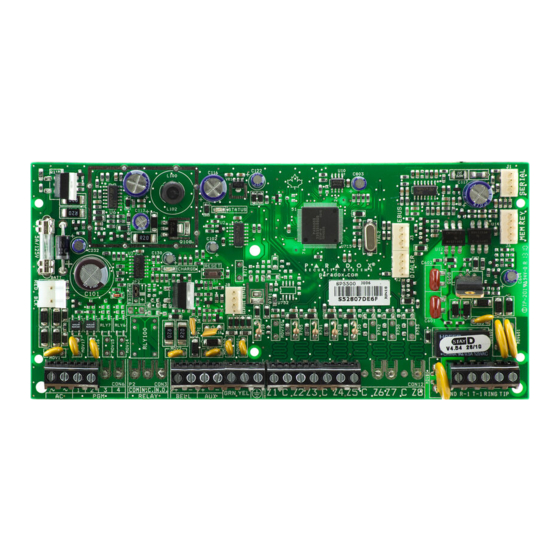
Page 9: Mg5050 / Mg5050 En Pcb Layout
PGMs are ground (-), or give out 12V (+) for In-Field Firmware upgrade through a 307USB Direct Connect Interface 2 Paradox Memory Key (PMC5) 8 Panel reset 2 EBUS (J3) and Dialer (J4) used with: 9 Zone Input: Refer to Single Zone Inputs on page 18 •... -
Page 10: Mg5075 Pcb Layout
Magellan & Spectra SP • Installation Guide MG5075 PCB Layout Do not cut, bend, or alter the antenna, and ensure that electrical wires do not cross over it, as this may affect signal reception. To provide maximum lightning protection we strongly recommend having separate earth connections for the dialer and zone... -
Page 11: Sp4000 Pcb Layout
8 Refer to AC Power & Backup Battery Connections section 1 Paradox Memory Key (PMC5) 9 The output will shutdown if the current exceeds 3A 2 EBUS (J3) and Dialer (J4) used with:... -
Page 12: Sp5500 Pcb Layout
In-Field Firmware upgrade through a 307USB Direct Connect Interface disconnect all loads from the output for at least 10 sec. before 7 Paradox Memory Key (PMC5) reconnecting any load back to the auxiliary output The sum of the current drawn from the must be limited to 1.3A. -
Page 13: Sp6000 Pcb Layout
In-Field Firmware upgrade through a 307USB Direct Connect Interface reconnecting any load back to the auxiliary output 7 Paradox Memory Key (PMC5) The sum of the current drawn from the must be limited to 1.3A. Exceeding this limit will overload the panel power supply BELL and lead to complete system shutdown. -
Page 14: Sp7000 Pcb Layout
In-Field Firmware upgrade through a 307USB Direct Connect Interface reconnecting any load back to the auxiliary output 7 Paradox Memory Key (PMC5) The sum of the current drawn from the must be limited to 1.3A. Exceeding this limit will overload the panel power supply BELL and lead to complete system shutdown. -
Page 15: Pcb Metal Box Installation
PCB Metal Box Installation The crosses and dotted line represent the PCB mounting location. If you need specific dimensions, contact Paradox Distributor Support. For UL recommended installation for the MG5000 only, place the PCB one notch lower than the mounting location. - Page 16 Magellan & Spectra SP • Installation Guide SP5500 (8x10”) SP6000 (11x11”) SP7000 (11x11”)
-
Page 17: Auxiliary Power Terminals
Information security is achieved by 256 bit encrypted, supervised communication (AES validation number is 986) which prevents unauthorized reading or modification of messages. Paradox alarm reporting systems are compatible with a variety of report code formats that are detailed in the Programming Guide. Bell Output Connection The BELL+ and BELL- terminals power bells, sirens and other warning devices requiring a steady voltage output during an alarm. -
Page 18: Single Zone Inputs
Magellan & Spectra SP • Installation Guide Single Zone Inputs Detection devices such as motion detectors and door contacts are connected to the control panel's zone input terminals. Figure 3 demonstrates single zone input terminal connections recognized by the panel. Once connected, the associated zone's parameters must be defined. Figure 3: Single Zone Input Connections... -
Page 19: Advanced Technology Zone (Atz) Connections
Magellan & Spectra SP • Installation Guide Advanced Technology Zone (ATZ) Connections The ATZ feature is a software oriented feature that enables two detection devices to be installed per hardwired input terminal. Each detection device has its own zone, displays its zone status on the keypad and sends its own alarm codes. Fire zones cannot be doubled. Figure 4: Advanced Technology Zone Connections... -
Page 20: Fire Circuits
Magellan & Spectra SP • Installation Guide Fire Circuits When a zone is programmed as a fire zone, the zone becomes normally open and requires an EOL resistor. If a line short occurs or if the smoke detector becomes active, whether the system is armed or disarmed, the control panel will generate an alarm. If a trouble occurs on a fire zone, the Fire Loop Trouble will appear in the keypad’s trouble display (See “Trouble Display”... -
Page 21: Programming Methods
Program the control panels remotely or on-site using the BabyWare Software (V2.80 or higher) for Windows®. For more information, contact your local Paradox Distributor or visit our web site at paradox.com. If you are using the BabyWare software, you must program the features (See “Settings for BabyWare Software” on page 61). -
Page 22: Configuring The Keypad Zone Number
Programming Using A Paradox Memory Key* Copy the sections of one control panel into the Paradox Memory Key (PMC5). Then copy the contents of the Memory Key into as many control panels as needed. Each panel is programmed in less than 3 seconds. -
Page 23: Lcd Keypad Labels
Magellan & Spectra SP • Installation Guide LCD Keypad Labels Input Keys Special Function Keys Alphanumeric Key Input Function A / B / C Insert space [stay] D / E / F Delete [sleep] G / H / I Delete whole entry [arm] J / K / L Toggle numeric/alphanumeric keys... - Page 24 Magellan & Spectra SP • Installation Guide Hebrew Keypad Letter Assignment Hebrew Special Characters Catalogue Greek Keypad Letter Assignment Greek Special Characters Catalogue Press key Press key Press key once twice three times A069...
- Page 25 Magellan & Spectra SP • Installation Guide Russian Keypad Letter Assignment Russian Special Characters Catalogue...
-
Page 26: Access Codes
Magellan & Spectra SP • Installation Guide Access Codes The control panel supports the following access codes: Installer Code [397]: Used to program all control panel settings except user access codes. The Maintenance code is similar to the Installer code. It can be used to enter programming mode, which allows you to pro- Maintenance Code [398]: gram all the features, options and commands except for the panel’s communication settings. -
Page 27: Lock Master Code
Magellan & Spectra SP • Installation Guide Partition 2 Assignment Sections [404] to [432]: User Codes 004 to 032 Option [2] OFF= Deny access to partition 2 (default) Option [2] ON= User code has access to partition 2 If the system is partitioned (See “Partitioning” on page 58), user codes with this option enabled can arm and disarm partition 2. If the system is not partitioned, the control panel ignores this option. -
Page 28: Stayd Mode
Magellan & Spectra SP • Installation Guide StayD Mode Overview • NOTE: StayD is automatically enabled when a path is programmed to a keypad. When deleting a wireless keypad from the system, the corresponding path zones will also be deleted. StayD simplifies your life and makes it safer by protecting you 24 hours a day, 7 days a week without ever having to disarm the system - even when entering an armed area. -
Page 29: Zone Programming
Magellan & Spectra SP • Installation Guide Zone Programming When programming zones, the zone assignments are dependent on the designation of the wireless transmitters, assignment of keypad zones, and the detection devices that are connected to the panel. For wireless assignment, See “Wireless Transmitter Programming” on page 36 or the Installer Quick Menu of the programming guide. - Page 30 Magellan & Spectra SP • Installation Guide Entry Delay 2 (Full Arm) Zones Sections [001] to [032]: Zones 1 to 32, First Digits = 04 Upon regular arming, the zone is Entry Delay 2 (See “Entry Delay 2 Zones” on page 29). Upon Stay/Sleep arming, the zone is bypassed by the system. See Zone Definition Status on page 32 for any exceptions.
- Page 31 Magellan & Spectra SP • Installation Guide Delayed Fire Zones Sections [001] to [032]: Zones 1 to 32, First Digits = 12 When a Delayed 24Hr. Fire zone opens, whether it is armed or disarmed, the control panel will react as Figure 10: Delayed 24Hr Fire Zone shown in Figure 10.
-
Page 32: Zone Definition Status
Magellan & Spectra SP • Installation Guide 24 Hr. Freeze Zones Sections [001] to [032]: Zones 1 to 32, First Digits = 21 When a 24Hr. Freeze zone opens, whether it is armed or disarmed, the control panel will immediately generate an alarm. This alarm is defined by the alarm type, configured in Zone Programming under zone options [4] and [5]. - Page 33 Magellan & Spectra SP • Installation Guide Auto Zone Shutdown Sections [001] to [032] = Zones 1 to 32 Option [1] OFF= Auto Zone Shutdown Disabled Option [1] ON= Auto Zone Shutdown Enabled for selected zone (default) If, in a single armed period, the number of alarms generated by a zone with the Auto Zone Shutdown option enabled exceeds the number defined by the Auto Zone Shutdown Counter, the control panel will no longer generate an alarm for that zone.
-
Page 34: Eol Zones
Magellan & Spectra SP • Installation Guide Force Zones Sections [001] to [032]: Zones 1 to 32 Option [8] OFF= Force Zone Disabled Option [8] ON= Selected Zone is Force Enabled (default) Any open Force Zones at the time of arming will be considered deactivated by the control panel. If during this period a deactivated zone is closed, the control panel will revert that zone to active status. -
Page 35: Keyswitch Programming
Magellan & Spectra SP • Installation Guide Keyswitch Programming Keyswitch Numbering On-board hardwire control panel zones only. Keyswitch Numbering allows you to assign any hardwired input in the system to any of the 32 keyswitch zones in the control panel. UL Note: Do not use keyswitches in UL Listed systems. -
Page 36: Wireless Features
Magellan & Spectra SP • Installation Guide Wireless Features The control panel(s) allows for the addition of up to thirty-two fully supervised wireless transmitters, and up to thirty-two programmable remote controls. Wireless Transmitter Programming The programming of the wireless transmitters (detectors and door contacts) is accomplished in two steps: 1. -
Page 37: Rf Jamming Supervision
Magellan & Spectra SP • Installation Guide RF Module Supervision Timer Settings Section [706]: Supervision Options Option [1] OFF= Check-in supervision interval is every 24 hours (default) Option [1] ON= Check-in supervision interval is every 80 minutes Option [1] defines the time period that the control panel will expect a check-in status signal from its assigned wireless transmitters. For example, if the timer is set to 80 minutes (option [1] = ON), the control panel will expect a check-in status signal to be sent from its assigned wireless transmitters within 80 minutes. -
Page 38: Wireless Keypad Assignment
Magellan & Spectra SP • Installation Guide Programming the Remote Control Buttons Sections [611] to [642]: Remote Controls 1 to 32 respectively. Each remote control can be programmed to perform up to 4 different actions. Each digit in sections [611] to [642] represents a button or combination of buttons. Digits 1 through 4 can be programmed, while digits 5 through 8 are reserved for future use and must be defined as empty (reminder: [SLEEP] = empty). -
Page 39: Wireless Keypad Options
Magellan & Spectra SP • Installation Guide Wireless Keypad Options Section [588]: Wireless Keypad Options If enabled, the panel can wait for each of its assigned wireless transmitters to send a status signal within a specified time to confirm their presence and functionality. Option [1] OFF= Keypad 1 Supervision Disabled Option [1] ON = Keypad 1 Supervision Enabled (default) Option [2] OFF= Keypad 2 Supervision Disabled... -
Page 40: Viewing The Repeater's Signal Strength
Magellan & Spectra SP • Installation Guide Viewing the Repeater’s Signal Strength Sections [548] to [549] Once the repeaters have been installed and assigned to the control panel, the signal strength of each repeater can be verified in sections [548] to [549]. Section [548] is the viewer for repeater 1 and section [549] is the viewer for the repeater 2. - Page 41 Magellan & Spectra SP • Installation Guide Section [552] (Repeater 1) and Section [562] (Repeater 2): Wireless Repeater Options Enable or disable the repetition of zone signals in these sections. Enabling these options for zones means that the repeater will retransmit any signals relevant to them.
- Page 42 Magellan & Spectra SP • Installation Guide Section [554] (Repeater 1) and Section [564] (Repeater 2): Wireless Repeater Options Enable or disable the repetition of zone signals in these sections. Enabling these options for zones means that the repeater will retransmit any signals relevant to them. Option [1] OFF= Repeat Wireless Zone 17 Signals (default) Option [1] ON = Repeat Wireless Zone 17 Signals Option [2] OFF= Repeat Wireless Zone 18 Signals (default)
- Page 43 Magellan & Spectra SP • Installation Guide Section [556] (Repeater 1) and Section [566] (Repeater 2): Wireless Repeater Options Enable or disable the repetition of 2WPGM signals in these sections. Enabling these options for 2WPGMs means that the repeater will retransmit any signals relevant to them.
-
Page 44: Arming And Disarming Options
Magellan & Spectra SP • Installation Guide Arming and Disarming Options Switch to Stay Arming if no Entry Delay is opened Section [741]: Partition 1, Section [742] = Partition 2 Option [5] OFF= Switch to Stay Arming Disabled (default) Option [5] ON= Switch to Stay Arming Enabled If a user Regular arms a partition, but does not exit through (open and close) an entry delay zone during the exit delay, the control panel can be programmed to switch from Regular arming to Stay arming. -
Page 45: Restrict Arming On Wireless Supervision Trouble
Magellan & Spectra SP • Installation Guide Restrict Arming on Wireless Supervision Trouble Section [703]: Arming/Disarming Options Option [7] OFF= Permit arming on wireless supervision failure (default) Option [7] ON= Restrict arming on wireless supervision failure If this option is enabled, the control panel will not arm the system if the control panel detects a wireless supervision trouble on one or more zones. The control panel will not arm the system until all wireless supervision trouble conditions are rectified. -
Page 46: One-Touch Arming
Magellan & Spectra SP • Installation Guide One-Touch Arming (Not to be used with UL installations) Section [703]: Options [1] to [3] Option [1] ON = Press & hold the key for One-touch Regular Arming. Option [2] ON = Press & hold the key for One-touch Stay Arming. -
Page 47: Alarm Options
Magellan & Spectra SP • Installation Guide Alarm Options Bell Cut-Off Timer Section [747] = Partition 1, [748] = Partition 2 000 = Disabled, 001 to 255 minutes, Default = 4 minutes, 5 minutes minimum for ULC installations After an audible alarm, the bell or siren will stop upon disarming of the partition or when the Bell Cut-Off Timer has elapsed, whichever comes first. Recycle Alarm After the Bell Cut-Off Timer and the Recycle Delay have elapsed, the control panel will re-verify the zone status. -
Page 48: Tamper Supervision On Panel (Mg5075 Only)
Magellan & Spectra SP • Installation Guide Tamper Supervision on Panel (MG5075 only) Section [700]: Supervision Options Option [8] OFF= Panel tamper supervision disabled Option [8] ON= Panel tamper supervision enabled (default) When the control panel detects a tamper, the control panel can generate an alarm or trouble, unless the Tamper Supervision is disabled. Keypad Panic Options Section [702]: General Options Option [1] OFF= Panic 1 Disabled (default) -
Page 49: Reporting And Dialer Settings
Magellan & Spectra SP • Installation Guide Reporting and Dialer settings The following section explains all the features and options that must be programmed in order for your security system to properly report system events to a monitoring station. When an event (e.g. zone in alarm) occurs in the system, the control panel verifies if a report code was programmed in the section corresponding to the event (except Ademco Contact ID “All Codes”). -
Page 50: System Trouble Report Codes
Magellan & Spectra SP • Installation Guide System Trouble Report Codes Section [865] to [869] When the system generates one of the instances listed below, the control panel can send the appropriate report code to the monitoring station identifying the type of system trouble. -
Page 51: Clear Reporting Codes
Magellan & Spectra SP • Installation Guide Clear Reporting Codes Section [966]: Clear Reporting Codes Option [1] OFF= Clear zone reporting codes Option [1] ON= Clear zone reporting codes (default) Option [2] OFF= Clear user reporting codes Option [2] ON= Clear user reporting codes (default) Option [3] OFF= Clear arm/disarm/alarm reporting codes Option [3] ON= Clear arm/disarm/alarm reporting codes (default) Option [4] OFF= Clear trouble reporting codes... -
Page 52: Reporting Formats
Magellan & Spectra SP • Installation Guide Reporting Formats Section [810]: 1st digit = Format for Phone #1, 2nd digit = Format for Phone #2 The panel can use a number of different reporting formats and each monitoring station telephone number can be programmed with a different reporting format. The first digit entered into section [810] represents the reporting format used to communicate with Monitoring Station Telephone Number 1, the second digit represents the reporting format used to communicate with Monitoring Station Telephone Number 2. -
Page 53: Dialing Method
Magellan & Spectra SP • Installation Guide If the Alternate Dial option is enabled, the control panel will dial the programmed backup telephone number (if enabled) after every failed attempt. If no backup telephone number is programmed, the control panel will never report to the backup telephone number. Example: The system is armed and zone 1 has been breached causing an alarm. -
Page 54: Recent Closing Delay
Magellan & Spectra SP • Installation Guide Recent Closing Delay Section [838] 000 = Disabled, 001 to 255 seconds, Default = Disabled If after having armed the system, an alarm is generated within the period defined by the Recent Close Delay, the control panel will attempt to transmit the Recent Close report code programmed in section [863]. -
Page 55: Zone Restore Report Options
Magellan & Spectra SP • Installation Guide Zone Restore Report Options Section [801]: Zone Options Option [2] OFF= Report On Bell Cut-Off (default) Option [2] ON= Report On Zone Closure With option [2] OFF, the panel will send the Zone Alarm Restore report codes to the monitoring station when the zone has returned to normal and the Bell Cut-Off Timer has elapsed. -
Page 56: Programmable Outputs
Magellan & Spectra SP • Installation Guide Programmable Outputs PGM is a programmable output that toggles to its opposite state (i.e. a normally open PGM will close) when a specific event has occurred in the system. For example, a PGM can be used to activate bells or strobe lights, open/close garage doors and much more. When a PGM activates, the control panel triggers any device or relay connected to it. -
Page 57: Pgm Programming
Magellan & Spectra SP • Installation Guide When armed, the PGM will pulse once every 30 seconds. Option [6] OFF= PGM Pulse on any alarm disabled (default) Option [6] ON= PGM Pulse on any alarm enabled This option sets the PGMs to pulse on any alarm. Option [7] OFF= PGM Pulse on any alarm Partition 1(default) Option [7] ON= PGM Pulse on any alarm Partition 2 Program PGMs to pulse during an alarm for either partition. -
Page 58: System Settings
Magellan & Spectra SP • Installation Guide System Settings Version Number Display Enter section [980] to view the version number of the panel. The first digit will appear. Press [ ] to scroll through each consecutive digit (the keypad will beep ENTER twice after every digit in the version number). -
Page 59: Installer Function Keys
Magellan & Spectra SP • Installation Guide Installer Function Keys To access the Installer Function keys, press: ] = Test Report: Send the “Test Report” report code programmed in section [875] to the monitoring station. ENTER INSTALLER CODE ] = Cancel Communication: Cancels all communication with BabyWare software or with the monitoring station until the next ENTER INSTALLER CODE STAY... -
Page 60: Display Entry Delay On Lcd Keypad (K32Lcd+)
Magellan & Spectra SP • Installation Guide Display Entry Delay on LCD keypad (K32LCD+) Section [701]: General System Options Option [7] OFF= Display entry delay on LCD keypad Option [7] ON= Display entry delay on LCD keypad (default) When this option is enabled the panel will display entry delays on the K32LCD+ keypad modules. Display Exit Delay on LCD keypad (K32LCD+) Section [701]: General System Options Option [8] OFF= Display exit delay on LCD keypad... -
Page 61: Settings For Babyware Software
Magellan & Spectra SP • Installation Guide Settings for BabyWare Software Note: BabyWare has not been verified by UL. Panel Answer Options The following two options define how the control panel answers an incoming call from a computer using the BabyWare Software for Windows®. Answering Machine Override Delay Section [902] 000 = Disabled, 000 to 255 seconds, Default = 030... -
Page 62: Automatic Event Buffer Transmission
Magellan & Spectra SP • Installation Guide Automatic Event Buffer Transmission Section [900]: Dialer Options Option [2] OFF= Auto Event Buffer Transmission Disabled (default) Option [2] ON= Auto Event Buffer Transmission Enabled When the event buffer reaches 90% capacity, the control panel will make two attempts to establish communication with a PC using the BabyWare software by [915] calling the PC Telephone Number programmed in section . -
Page 63: User Operation
Magellan & Spectra SP • Installation Guide User Operation Alarm Display If an alarm has occurred on a zone, the respective zone LED will flash, the [ ] key will light up, and the zones will be stored in memory. These respective LEDs will continue to flash until disarming even if the zones are restored. -
Page 64: Index
Index Call Back Feature ........................62 Numerics Cancel Auto-Arm Report Code ..................49 Charge Current ........................58 24 Hr. Burglary Zones ......................31 Closing Delinquency ......................54 24 Hr. Buzzer ..........................31 Cold Start Report Code ......................50 24 Hr. Freeze Zones ........................ 32 Configuring The LED Keypads ................... - Page 65 Number of Rings ........................60 Numbers .............................53 Ground ............................7 One-Touch Arming .........................46 Hardware Reset ........................58 Report Code ........................49 Options Alarm ..........................47 Arming and Disarming ....................44 Input Numbers Auto-Arming ........................45 Keyswitch Numbering ....................35 User code ........................26 Installation ........................... 7 Zone ..........................32 Installer Override Answering Machine .....................61 Code ..........................26...
- Page 66 Test Report ........................50 Termination ..........................46 Report Code, Special Alarm Test Report Auto Zone Shutdown ....................49 Automatic ........................54 Auxiliary Panic ....................... 49 Report Code ........................50 Duress ..........................49 Timed Auto-Arming ......................45 Emergency Panic ......................49 Report Code ........................
- Page 68 The whole Paradox team wishes you a successful and easy installation. We hope this product performs to your complete satisfaction. Should you have any questions or comments, please contact us at support@paradox.com. Additional information can be found on our website www.paradox.com/support...
Need help?
Do you have a question about the Magellan MG5050E and is the answer not in the manual?
Questions and answers