WaterCare TotalCare Series Installation Instructions & Owner's Manual
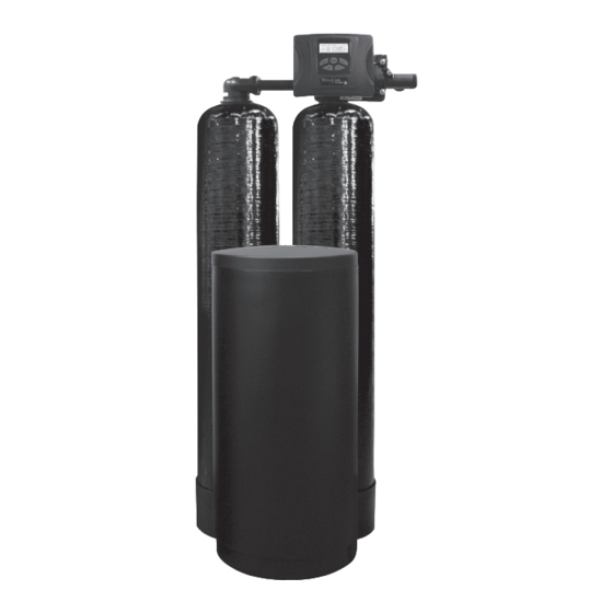
Twin water softeners and conditioners
Hide thumbs
Also See for TotalCare Series:
- Installation instructions & owner's manual (32 pages) ,
- Owner's manual (36 pages) ,
- Installation instructions & owner's manual (32 pages)
Advertisement
Table of Contents
- 1 Table of Contents
- 2 Bypass Valve
- 3 Installation
- 4 Programming Procedures
- 5 Operating Displays and Maintenance
- 6 Start-Up Instructions
- 7 Troubleshooting Guide
- 8 Service Instructions for Transfer Assemblies
- 9 Replacement Parts
- 10 Specifications
- 11 Warranty
- 12 Quick Reference Guide
- 13 Hardness
- Download this manual
Advertisement
Table of Contents

Related Manuals for WaterCare TotalCare Series


Summary of Contents for WaterCare TotalCare Series
- Page 1 TotalCare , CareSoft Elite ® ® CareSoft Pro Series ® Twin Water Softeners and Conditioners For Models: • TC1-TW • TC2-TW • CSE-TW • CSP-TW • CSERC-TW • CSPRC-TW...
-
Page 2: Table Of Contents
Water conditioners do not remove nitrates or coliform bacteria, this requires specialized equipment . Your WaterCare twin water softeners and conditioners are precision built, high quality products . These units will deliver conditioned water for many years to come, when installed and operated properly . Please study this manual carefully and understand the cautions and notes before installing . - Page 3 PRE-INSTALLATION INSTRUCTIONS The manufacturer has preset the water treatment unit’s sequence of cycles, cycle times, salt dose, exchange capacity and salt dose refill time. THE DEALER SHOULD... THE INSTALLER SHOULD... THE HOMEOWNER SHOULD... •Read this page and guide the installer •Program installer settings including hardness, •Read Programming Procedures section.
-
Page 4: Bypass Valve
BYPASS VALVE The bypass valve is typically used to isolate the control valve from the plumbing system’s water pressure in order to perform control valve repairs or maintenance. The 1” full flow bypass valve incorporates four positions, including a diagnostic position that allows a service technician to have pressure to test a system while providing untreated bypass water to the building. -
Page 5: Installation
INSTALLATION GENERAL INSTALLATION & SERVICE WARNINGS The control valve, fittings and/or bypass are designed to accommodate minor plumbing misalignments. There is a small amount of “give” to properly connect the piping, but the water treatment unit is not designed to support the weight of the plumbing. Do not use Vaseline, oils, other hydrocarbon lubricants, or spray silicone anywhere. - Page 6 INSTALLATION 7. INSTALLING GROUND: To maintain an electrical ground in metal plumbing of a home’s cold water piping (such as a copper plumbing system), install a ground clamp or jumper wiring. NOTE: If replacing an existing unit, also replace the ground clamps/wire. If removing a unit, replace the piping with the same type of piping as the original to assure plumbing integrity and grounding.
- Page 7 This page intentionally left blank.
-
Page 8: Programming Procedures
PROGRAMMING PROCEDURES: 1. Set Time of Day Typically, time of day should only need to be set after extended power outages or when daylight saving time begins or ends. If an extended power outage occurs, the time of day will flash on and off indicating that the time should be reset. To set the clock: STEP 1 –... - Page 9 SERVICE ALARM PROGRAMMING PROCEDURES: – STEP 7 – ALARM BUZZER: Use the buttons to turn the alarm ON or OFF. Unit is set to ON by default. ALARM BUZZER Alarm will sound after a regeneration warning the owner of possible valve errors or other issues. This alarm is a short 0.5 second burst every 3 seconds.
-
Page 10: Operating Displays And Maintenance
START-UP INSTRUCTIONS FLUSHING OF SYSTEM: To flush the system of any debris and air after installation is complete, please perform the following steps: 1. Rotate bypass handles to the bypass mode (Fig. 2 on page 4) . 2. Turn on inlet water and check for leaks in the newly installed plumbing. 3. - Page 11 OPERATING DISPLAYS AND MAINTENANCE: 1. GENERAL OPERATION: When the system is operating, one of six displays may be shown and will alternate with the installing dealer’s name and phone number for future service. Pressing NEXT will alternate between the displays. 1.
-
Page 12: Start-Up Instructions
OPERATING DISPLAYS AND MAINTENANCE: 5. POWER LOSS AND BATTERY REPLACEMENT: If an extended power outage occurs, the control valve will retain the time of day settings until the board’s battery is depleted. Once the battery is depleted, the display will appear dark and absent of any information. If this occurs, following these steps will determine if the problem is a low battery or a board failure. -
Page 13: Troubleshooting Guide
TROUBLESHOOTING GUIDE PROBLEM CAUSE CORRECTION A. Depleted battery A. See Operating Display and Maintenance section B. Control valve power adapter not plugged into outlet B. Plug power adapter into outlet or connect or power cord end not connected to PC board power cord end to PC board connection connection 1. - Page 14 TROUBLESHOOTING GUIDE PROBLEM CAUSE CORRECTION A. Turn bypass handles to place bypass in A. Bypass valve in bypass position service position B. Meter is not connected to meter connection on PC B. Connect meter to three pin connection labeled 7. Control valve does not board METER on PC board regenerate automatically...
- Page 15 TROUBLESHOOTING GUIDE PROBLEM CAUSE CORRECTION A. Injector is plugged A. Remove injector and clean or replace B. Faulty regenerant piston B. Replace regenerant piston C. Regenerant line connection leak C. Inspect regenerant line for air leak 12. Control valve fails to D.
- Page 16 TROUBLESHOOTING GUIDE PROBLEM CAUSE CORRECTION A. Check motor connections then Press NEXT and REGEN buttons for 3 seconds to resynchronize A. Motor failure during a regeneration software with piston position or disconnect power supply from PC board for 5 seconds and then reconnect.
- Page 17 TROUBLESHOOTING GUIDE PROBLEM CAUSE CORRECTION 20. Err – 109 A. Invalid motor state detected A. Replace PC board 21. Err – 201 A. Invalid regeneration cycle step detected A. Replace PC board A. Check for low flow leak. Press NEXT and REGEN A.
-
Page 18: Service Instructions For Transfer Assemblies
SERVICE INSTRUCTIONS TRANSFER CAP ASSEMBLIES SERVICE Release locking tabs INSTRUCTIONS from each side to remove back plate. 1 . The backplate of the control valve must first be removed to allow access to the transfer cap assembly . 2 . Hold slight downward pressure on the top left corner of the backplate while using a thin flat screwdriver or knife blade to push in on the locking tabs . - Page 19 SERVICE INSTRUCTIONS 13 . Prior to reinstalling the discs, the drive shaft should be removed and the O-rings cleaned, inspected and lubricated with Dow #7 silicone grease . The shaft can now be installed into the disc prior to installation . 14 .
-
Page 20: Replacement Parts
REPLACEMENT PARTS: FRONT COVER AND DRIVE ASSEMBLY Item No. Part No. Description Qty. CV3837-01XB TotalCare cover CV3837-01 CareSoft Elite/CareSoft Pro cover CV3107-1 Motor CV3002A Drive assembly (Includes #5 and #6) — CV4050WB PC board (used on chlorine generator models) CV4062WX PC board (standard) CV3110 Drive gear, 12 x 36... - Page 21 REPLACEMENT PARTS PISTON ASSEMBLY Item No. Part No. Description Qty. CV3005 1” spacer stack assembly CV3004 Drive cap assembly CV3135 O-ring 228 CV3011 1” piston assembly downflow CV3011-01 1” piston assembly upflow CV3174 Regenerant piston CV3541 Drive backplate IN/OUT HEAD (FOR TANK B) Item No.
- Page 22 REPLACEMENT PARTS...
- Page 23 REPLACEMENT PARTS TWIN TRANSFER Item No. Part No. Description Qty. CV3470 Screw, BHC 1/4- 20 x 1 SS CV3724 Washer, flat SS 1/4 CV4005-01 T1 transfer cap assembly CV4029 O-ring 236 CV4015 T1 transfer spring CV4014 T1 transfer spring support CV4036 T1 rotor disk assembly CV3105...
- Page 24 REPLACEMENT PARTS BYPASS VALVE Item No. Part No. Description Qty. CV3006 Bypass assembly CV3147 Bypass handles BRINE ELBOW ASSEMBLY Item No. Part No. Description Qty. CV3195-01 Refill port plug assembly CH4615 Elbow locking clip CV4144 3/8” Elbow, Parker fitting Loosens Injector And CV3163 O-ring 019 Bypass Caps...
- Page 25 REPLACEMENT PARTS INJECTOR ASSEMBLIES Item No. Part No. Description Qty. CV3176 Injector cap CV3152 O-ring 135 CV3177-01 Injector screen CV3010-1Z Injector assembly plug CV3010-1A A injector assembly, BLACK CV3010-1B B injector assembly, BROWN CV3010-1C C injector assembly, VIOLET D injector assembly, RED CV3010-1D CV3010-1E E injector assembly, WHITE...
- Page 26 REPLACEMENT PARTS DRAIN LINE ASSEMBLY 3/4” DRAIN LINE ASSEMBLY 1” Item No. Part No. Description Qty. Item No. Part No. Description Qty. CH4615 Elbow locking clip CH4615 Elbow locking clip CPKP10TS8-BULK Optional insert, 5/8” tube CV3166 Drain FTG body 1 CV3192 Optional nut, 3/4”...
- Page 27 REPLACEMENT PARTS BRINE TANK ASSEMBLY Item No. Part No. Description Qty. CG2191-84 Brine tank cover, injection molded WR CG2180 Brine tank cover, standard CH1095-01 Optional 18” diameter salt grid CH1080 Optional 24” diameter salt grid CG21833CB1C00 18” x 33” brine tank, black CG21840CB1C00 18”...
- Page 28 INSTALLATION FITTING ASSEMBLIES Fitting Installation Instructions • Installation fittings are designed to accommodate minor plumbing misalignments, but are not designed to support the weight of a system or the plumbing. • Slide nut on first, then the split ring and O-ring. •...
- Page 29 INSTALLATION FITTING ASSEMBLIES NOTE: Not all available fi � ngs are Item No. Part No. Description Qty. displayed below. Contact For All Assemblies CV3151 Nut, 1” quick connect manufacturer for op� onal CV3150 Split ring fi � ngs. CV3105 O-ring 215 1”...
- Page 30 This page intentionally left blank.
-
Page 31: Specifications
CSP-1044TW CSP-1054TW CSP-1354TW CSP-1465TW CSP-1665TW CSPRC-1054TW CSPRC-1354TW Backwash Brine & Rinse Rinse Brine Refi ll Regenerant (lbs.) Total (min.) Manufactured for WaterCare • 1900 Prospect Court • Appleton, WI 54914 • Phone: 920-739-9401 • Fax: 920-739-9406 SPE-WC TW SOFT RevA0119... - Page 32 GAL. MIN. GAL. MIN. GAL. MIN. GAL. MIN. GAL. Backwash Brine & Rinse Rapid Rinse Brine Refi ll Total Manufactured for WaterCare • 1900 Prospect Court • Appleton, WI 54914 • Phone: 920-739-9401 • Fax: 920-739-9406 SPE-WC TW COND RevA0219...
-
Page 33: Warranty
Congratulations. You have purchased one of the fi nest water treatment systems available. In the unlikely event of a problem due to defects in material and workmanship, Water-Right proudly warrants our WaterCare water ® conditioners and softeners to the original owner, at original installation location, when installed in accordance with Water-Right specifi... -
Page 34: Quick Reference Guide
QUICK REFERENCE GUIDE: GENERAL OPERATION MANUAL REGENERATION REGEN TODAY and TIME OF DAY will flash alternately if a regeneration NOTE: For softeners, if brine tank does When the system is operating, one of six displays will be shown: is expected tonight. 1 . -
Page 35: Hardness
QUICK REFERENCE GUIDE: ADJUST HARDNESS, DAYS BETWEEN REGENERATION, TIME OF REGENERATION AND ALARM BUZZER For initial set-up or to make adjustments, please complete the following steps . SERVICE ALARM 1 . Accessed by pressing and + button simultaneously NEXT 2 . Adjust hardness using + and — buttons 3 . - Page 36 1900 Prospect Court • Appleton, WI 54914 Phone: 920-739-9401 • Fax: 920-739-9406 © 2020 WaterCare All rights reserved. MAN-WC TWIN RevA0120...
Need help?
Do you have a question about the TotalCare Series and is the answer not in the manual?
Questions and answers