BOCK FK40 Seroes Maintenance Manual
Hide thumbs
Also See for FK40 Seroes:
- Maintenance manual (58 pages) ,
- Assembly instructions manual (28 pages)
Table of Contents
Advertisement
Advertisement
Table of Contents

Related Manuals for BOCK FK40 Seroes


Summary of Contents for BOCK FK40 Seroes
- Page 2 standard there your team at...
-
Page 3: Table Of Contents
Contents Page Introduction Safety instructions Product description Short description, nameplate, type code Main and functional parts Dimension drawing, connections Technical data Maintenance Function checks, oil level check, oil change Operation of the shut-off valves Fault diagnosis / Remedying the malfunction General, function faults - symptoms Compressor stand still Compressor cutoff... - Page 4 Contents Page Checking the components of the compressor for damage / wear Limiting values for wear Cylinder liners Crankshaft Pistons Connecting rods Valve plates Oil pump Oil filter / suction filter Internal safety valve Assembly of the compressor 1 Fitting the roller bearings 2 Fitting the sight glass, the plugs and the internal safety valve 3 Assembly of the pistons / connecting rods 4 Fitting the piston / connecting rod sets...
-
Page 5: Introduction
Introduction Vehicle compressors Series FK 40 of Bock are among the most wide-spread machines used for bus A/C applications. The criteria that speak for choosing a FK 40 compressor are its compact dimensions, its low weight, the wide capacity spectrum together with the high operating safety and service-friendliness. -
Page 6: Product Description
Product description Product description Series FK 40 vehicle compressors are designed for mobile applications. FK 40 - FK 40 - FK 40 - A/C compressor A/C compressor Deep-freeze compressor for R134a for R134a for R404A (R22) = 3000 rpm = 3500 rpm = 2600 rpm Peak value = 3500 rpm Short description... -
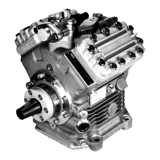
Page 7: Main And Functional Parts
Main and functional parts Figure 1 Figure 2 9. Nameplate 1. Discharge shut-off 2. Valve plate 10. Connection for heat protection thermostat 3. Cylinder cover 11. Oil filling plug 12. Sight glasses for oil (2x) 4. Compressor casing 13. Oil drain plug 5. -
Page 8: Dimension Drawing, Connections
Dimension drawing Connections FK 40/390 FK 40/470 FK 40/560 FK 40/655 [mm] SV Suction shut-off valve, pipe dia.(L)* [Inches] [mm] DV Discharge shut-off valve, pipe dia. (L)* [Inches] Suction side port, not lockable [Inches] 1/8" NPTF Suction side port, lockable [Inches] 7/16"UNF Pressure side port, not lockable... -
Page 9: Technical Data
Technical data No. of cylinders Mass moment of inertia of the driving unit [kgm 0,0043 Lubrication Forced lubrication Oil pump Bidirectional Type of oil for R134a, R404A FUCHS Reniso Triton SE 55 Type of oil for R22 FUCHS Reniso SP 46 Oil filling [liters] Rotational speed see limits of application... -
Page 10: Maintenance
FUCHS Reniso Triton SE 55 FUCHS SEZ 32 / 68 / 80 SHELL Clavus R 46 ICI Emkarate RL 46 S Information about other suitable oils should be taken from Bock lubricant tables. Information may also be retrieved from www.bock.de. - 10 -... -
Page 11: Operation Of The Shut-Off Valves
Operation of the shut-off valves Position A Opening the shut-off valve a) Spindle 1: Turn to the left (ccw) until the end stop ® Shut off valve fully open / Service port 2 closed (Position A), Fig. Position B Opening the service port (2) b) b) Spindle 1: Turn 1/2-1 turn to the right ®... -
Page 12: Fault Diagnosis / Remedying The Malfunction
Fault diagnosis Fault diagnosis In case of malfunctions during compressor operation we recommend to prepare a measurement record for aiding the fault search: Pressure measurement: Discharge side, suction side, oil pressure Temperature measurement: Compressor casing, discharge end temperature, suction gas overheating According to the expected cause of the fault it may be necessary to check the electrical system for faults in the control. -
Page 13: Compressor Cutoff
Compressor cutoff Compressor starts and stops again Possible cause Symptom Remedy Suction pressure too low: Cutoff though low- pressure switch - Adjust the switching points or replace - Check the setting of the low pressure switch switch - Open shut-off valve - Suction valve of the compressor closed - Check operating conditions - Capacity of compressor too large... -
Page 14: Cooling Performance Too Low
Cooling performance too low Possible cause Symptom Remedy - Remove the cause - Evaporator iced up Suction pressure too high - Expansion valve not functioning properly - Check valve setting; replace valve, if necesaary - Lack of compressor capacity - Check the functioning of the compressor by evacuating to vacuum. -
Page 15: Oil Problems
Oil problems Possible cause Symptom Remedy - see “Oil foams" Oil pressure too low - Refrigerant in oil - Add oil and search for the cause of - Too little oil in compressor oil loss - Clean / replace oil filter - Oil filter dirty / blocked Change oil - Check the laying of pipes... -
Page 16: Malfunction Of The Electromagnetic Clutch
Malfunction of the electromagnetic clutch Possible cause Symptom Remedy Clutch not switching - No voltage applied - Apply voltage and check Clutch slipping too - Voltage too low - Keep the voltage at 12 or 24 long, getting hot, Volts (check vehicle network) smoking and squeaking - Driving power too high - Check operating conditions... -
Page 17: Installation Of Service Kits
Switch of the machine and guard it against switching on Close the discharge and suction shut-off valves Relieve the compressor from system pressure Use only genuine Bock spare parts. After the work is finished: Connect the safety switch and check its function... -
Page 18: Leak Oil Collection Ring, Part No. 80019
Leak oil collection ring (Part No. 80019) Leak oil collection ring Procedure: Remove the leak oil collection ring (see Fig. 1) The repair kit contains two felt inlays (Pos. 2 and Pos. 3, see Fig. 2) If the bearing flange with one oil pocket is installed Pos. -
Page 19: Shaft Seal, Part No. 80023
Shaft seal (Part No. 80023) Removal: Dismount the drive/magnetic clutch from the compressor. Remove the Woodruff key from seat at the shaft end Remove the leak oil collection ring (9) and the felt inlay (8a or 8b, according to the type) (for this, see Fig. - Page 20 Capacity regulation The capacity regulation takes place through the turning off of the suction gas flows by means of a solenoid valve on the cylinder cover. For this, the valve is activated electrically by a thermostat or pressostat. During normal operation the solenoid is de-energized and the suction gas channel in the valve plate and in the cylinder cover is open.
-
Page 21: Valve Plate
Valve plate Compressor type Parts kit (Part No.) Compressor type Parts kit (Part No.) 80240 FK 40/390 N 80240 FR 40/390 TK FK 40/470 N 80240 FR 40/470 TK 80240 FK 40/560 N 80241 FR 40/560 TK 80241 FK 40/655 N 80241 FK 40/655 TK 80241... - Page 22 Removal (see Fig. 7): Unscrew the screws (1) from the cylinder cover (2) and dismount cylinder cover (2) with valve plate (4) Remove the gasket residues from the body of the compressor. Reminder: Don’t let any gasket residues fall into the compressor Installation (see Fig.
-
Page 23: Electromagnetic Clutch
Electromagnetic clutch Assembly instruction for electromagnetic clutch For the drive of A/C compressors in buses, mainly electromagnetic clutches are used. The followings assembly instructions for clutch type LA 16 is representative for clutches which are mounted onto the front bearing flange of the compressor. Assembly instruction for electromagnetic clutch Type LA 16 The front bearing flange has a locationg face 148h8 for fitting the solenoid of the electro-... - Page 24 Reminder: Arrange the cable (8) so that it doesn’t touch hot parts (e.g. protection pipe). Tmax = 105°C! Remove the K-circlip (5) and the clamping screw (4) from the rotor assembly (3). Looking through the rotor hole, pay attention to the correct seating of the Woodruff key in the rotor slot.
-
Page 25: Compressor Defects
Compressor defects Compressor defects Compressor defects may have various causes. The table below is meant to aid you while analyzing the cause of the breakdown by means of the defective compressor parts found. Thus, the specific remedying of the cause of the breakdown is facilitated. Possible causes Compressor part Remedy... -
Page 26: Disassembly Of Compressor
Preparation: Necessary tools Reminder! For the removal and installation of the internal safety valve the BOCK special tool Part No. 09524 is necessary! Pos. -
Page 27: Removal Of All Shut-Off Valves And Blind Flanges
Step Removal of all shutt-off valves and blind flanges Parts list position: 2060, 2070, 232 Tools: Spanner 17 mm, Allen key 6 mm Pos. in Working course parts list Unscrew the fixing screws of shut-off valves 330, 210 Remove the shut-off valves and the gaskets 230, 210 Remove the suction filter and the gasket Remove the screws from the blind flange... -
Page 28: Removal Of Oil Filter
Step Removal of the oil filter Parts list position: 2130 Tools: Oil collection container, spanner 19 mm, Allen key 10 mm Pos. in Working course parts list Drain the oil from the compressor into a suitable container Unscrew the plug Remove the gasket Unscrew the oil filter Fig. -
Page 29: Removal Of The Cylinder Cover And Of The Valve Plates
Step Removal of the cylinder cover and valve plates Parts list position: 170, 2000 (N / TK-versions), 1940, 2900 (K Version) Tools: Spanner 17 mm In order to prevent any mix-up during reassembly, mark the cylinder cover and the valve plates belonging together clearly and in a wipe-resistant fashion. Pos. -
Page 30: Removal Of The Shaft Seal
Step Removal of the shaft seal Parts list position: 2010 Tools: Oil collection container, Allen key 6 mm For a detailed description see also the section on the Removal of the shaft seal on page 19! Pos. in Working course parts list Place the oil collection container under the shaft seal area. -
Page 31: Removal Of The Oil Pump
Step Removal of the oil pump Parts list position: 2020 Tools: Spanner 13 mm Pos. in Working course parts list Unscrew the screws Remove the oil pump and gasket 460, 470 Fig. 16a Fig. 16b - 31 -... -
Page 32: Removal Of The Baseplate
Step Removal of the baseplate Parts list position: 20 Tools: Oil collection pan, spanner 13 mm Pos. in Working course parts list Place the compressor into the oil collection pan and turn it sideways Unscrew the screws from the baseplate Remove the baseplate and the gasket 20, 30 Fig. -
Page 33: Disassembly Of The Connecting Rods From The Crankshaft
Step Disassembly of the connecting rods from the crankshaft Parts list position: 2100 Tools: Spanner 10 mm In order to prevent any mix-up during reassembly, mark the connecting rods and caps belonging together clearly and in a wipe-resistant fashion. Pos. in Working course parts list Unscrew the hexagon head screws from the connecting rod cap. -
Page 34: Removal Of The Front Bearing Flange
Step Removal of the front bearing flange Parts list position: 2140 Tools: Allen key 6 mm Pos. in Working course parts list Unscrew the screws Remove the front bearing flange, gasket, and O-ring 730, 740, 745 Fig. 19a Fig. 19b - 34 -... -
Page 35: Removal Of The Crankshaft
Step Removal of the crankshaft Parts list position: 2050 Tools: --- Pos. in Working course parts list Pull out the crankshaft carefully in direction of the front bearing flange Fig. 20a Fig. 20b - 35 -... -
Page 36: Removal Of The Pistons And Connecting Rods
Step Removal of the pistons and connecting rods Parts list position: 2040 Tools: Seeger circlip plier From C 8-13 mm Pos. in Working course parts list Mark the piston and the cylinder bore belonging together Remove the piston / connecting rod in direction of baseplate Remove the seeger circlip of the piston pins Push the piston pins out of the pistons and remove pistons In order to prevent mix-ups, fasten the connecting rod... -
Page 37: Removal Of The Remaining Parts
Step Removal of the remaining parts Parts list position: - Tools: Spanner 13, 14, 30 or 36 mm, Bock special tool, Part no. 09524 Pos. in Working course parts list Dismount the sight glass (use 30 mm or 36 mm spanner according to the type) Remove O-ring Remove the 1/8”... -
Page 38: Removal Of The Roller Bearings
Step Removal of the roller bearings Parts list position: 2150 Tools: Pulling apparatus Pos. in Working course parts list 2150, 730 With the pulling apparatus pull out the roller bearing from the front bearing flange. Use oil, if necessary! If a pulling apparatus is not available, the front bearing flange may be heated for approx. 15 minutes in a pre-heated (220°C) baking oven. -
Page 39: Cylinder Liners
Checking the compressor parts Checking compressor parts for damages / wear Before re-using removed compressor parts we recommend that they be checked for usability. The wear limits listed below should be taken into consideration Wear limits maximum allowable bearing play: 1.) Piston-cylinder bore 0,13 mm 2.) Connecting rod-piston pin 0,03 mm... -
Page 40: Pistons
Pistons There should be no visible damages on the piston crown and the piston walls. The grooves for the piston rings must be clean and undamaged. Check the condition of the piston rings for wear, fractures and other irregularities. Connecting rods There should be no damages on bearing surfaces. -
Page 41: Oil Filter / Suction Filter
The filter screen must be in an undamaged condition. Dirt and residues have to be removed. If necessary, the filter have to be cleaned with compressed air or replaced with new ones. Internal safety valve (Use Bock special tool, Part No. 09524!) The internal safety valve must be replaced after it has operated. -
Page 42: Fitting The Roller Bearings
Asembly of compressor Step Fitting the roller bearings Parts list position: 2150 Tools: Pressing apparatus Pos. in Working course parts list · Heat the bearing flange / compressor casing for approx. 20 minutes in a pre-heated (120°C) baking oven. · Press the roller bearings onto the compressor casing and the front bearing flange. WATCH OUT! Parts are hot! Use protective gloves! Use tolerance ring if the bearing seat has a groove! Pressing tool... - Page 43 · Screw on the sight glass with oiled O-ring to the compressor body. · Screw on the 1/4" NPTF plugs. · Screw on the 1/8” NPTF plugs. · Screw on the safety valve by means of the Bock special tool into the suction channel. Fig. 30a Fig. 30b Fig.
-
Page 44: Assembly Of The Pistons / Connecting Rods
Step Assembly of the pistons / connecting rods Parts list position: 2040 Tools: Seeger circlip plier Form C 8-13 mm Pos. in Working course parts list · Assembly the pistons with the connecting rods (in the reverse sequence of the disassembly of compressor, Step 7) ·... -
Page 45: Fitting The Piston / Connecting Rod Sets
Step Fitting the piston / connecting rod set Parts list position: 2040 Tools: Spanner 10 mm Take the markings of each part into account (see Disassembly, Step 7 on page 33) Pos. in Working course parts list 2100 · Remove the connecting rod cap from the preassembled connecting rod assembly and mark it. -
Page 46: Fitting The Crankshaft
Step Fitting the crankshaft Parts list position: 2050 Tools: - Pos. in Working course parts list · Fit the crankshaft so that the drive journal engages into the pump gear. Fig. 33 -46-... -
Page 47: Installation Of The Front Bearing Flange
Step Installation of the front bearing flange Parts list position: 2140 Tools: Allen key 6 mm Observe the tightening torques (see Table on page 55)! Pos. in Working course parts list · Apply oil to the O-ring and place it into the groove in the bearing flange ·... -
Page 48: Assembly Of The Inserted Connecting Rods / Pistons
Step Assembly of the inserted connecting rods / pistons Parts list position: 2040 Tools: Piston ring plier, spanner 10 mm Pay attention to the correct pairing of connecting rods and connecting rod caps! Replace connecting rod cap screws or in the case of reusing put on a sticker! Observe the tightening torques (see Table on page 55)! Pos. -
Page 49: Installation Of The Oil Pump
Step Installation of the oil pump Parts list position: 2020 Tools: Spanner 13 mm Observe the tightening torques (see Table on page 55)! Pos. in Working course parts list · Install the oil pump with oiled gasket into the body with the inscription “TOP” facing upwards! 460, 470 Pay attention to the position of the holes in the gasket (Fig. -
Page 50: Fitting The Shaft Seal
Step Fitting the shaft seal Parts list position: 2010 Tools: Allen key 6 mm Watch out! Avoid damages! Pay attention to the markings! Apply a little oil to the parts! Observe tightening torques (see Table on page 55)! Pos. in Working course parts list ·... -
Page 51: Installation Of The Baseplate
Step Installation of the baseplate Parts list position: 20 Tools: Spanner 13 mm Observe the tightening torque (see Table on page 55) ! Pos. in Working course parts list 20, 30, 40 Install the baseplate with gasket and tighten the M8x30 screws. Pay attention to the tightening sequence of the baseplate screws! Fig. -
Page 52: Installation Of The Oil Filter
Step Installation of the oil filter Parts list position: 2130 Tools: Allen key 10 mm, Spanner 19 mm Observe the tightening torque (see Table on page 55)! Pos. in Working course parts list With the Allen key, screw on the oil filter into the hole in the body and tighten it. Install gasket. -
Page 53: Installation Of The Cylinder Cover And Valve Plates
Step Installation of the cylinder covers and valve plates Parts list position: 170, 2000 (N / TK versions), 1940, 2900 (K version) Tools: Spanner 17 mm Install only the cylinder covers and valve plates which belong together, avoid mix-ups! Observe the tightening torques (see Table on page 55)! Pos. -
Page 54: Installation Of The Shut-Off Valves And Blind Flanges
Step Installation of the shut-off valves and blind flanges Parts list position: 2060, 2070, 232 Tools: Spanner 17 mm, Allen key 6 mm Apply oil to gaskets; observe tightening torques (see Table on page 55)! Use screws of correct length for the installation of the intermediate flanges! Pos. -
Page 55: Checking The Compressor
Checking the compressor Working course 1. Evacuation/leak check of compressor Connect the discharge and suction sides of the compressor to a vacuum pump Evacuate the compressor from both sides; vacuum < 1,5 mbar. Check increase in pressure. In case there is an increase in pressure, check the compressor for leaks und evacuate again. Fill in the stipulated amount of oil (2,0 liters). -
Page 56: Spare Parts List
Spare parts list FK (X) 40/... Pos. Designation Version Piece Baseplate N, K, TK 03876 03876 03876 03876 Baseplate gasket N, K, TK 06721 06721 06721 06721 N, K, TK 06244 06244 06244 06244 M8x30 Hexagon head screw N, TK 05695 Lower gasket Valve plate, Ø... - Page 57 FK (X) 40/... Pos. Designation Version Piece N, K, TK 04367 Soldering gland Ø 28 N, K, TK 05313 Soldering gland Ø 35 05313 05313 Oil pump, complete N, K, TK 07990 07990 07990 07990 N, K, TK 05094 05094 Gasket, oil pump + bearing flange, rear 05094 05094...
-
Page 58: Repair Kits Parts List
Repair set parts list FK (X) 40/... FK (X) 40/... FK (X) 40/... Designation Pos. Version Piece N, TK 2000 SET Valve plate 80240 80241 80240 80241 N, K, TK 2010 SET Shaft seal 80023 80023 80023 80023 N, K, TK 2020 SET Oil pump 80017... -
Page 59: Parts List For Optional Accessories
Parts list, optional accessories FK (X) 40/... Pos. Designation Version Piece 3200 SET Capacity regulator LR 87, 24V N, TK with cylinder cover 08704 08704 08704 08704 N, TK 03383 03383 03383 03383 3220 Cylinder cover for capacity regulator, with bushing Upper gasket valve plate N, TK 06730...
Need help?
Do you have a question about the FK40 Seroes and is the answer not in the manual?
Questions and answers