Table of Contents
Advertisement
Quick Links
Advertisement
Table of Contents

Related Manuals for Lillbacka Powerco FINN POWER CM75PH


Summary of Contents for Lillbacka Powerco FINN POWER CM75PH
- Page 3 The material in this documentation is subject to change without notice. Keep this manual for future needs. The machine has been designed for cutting hydraulic hoses. Lillbacka Powerco shall not be held liable for any product which has been cut with the machine. The machine has been designed to operate in room temperature, in dry indoor conditions and in sufficient illumination.
-
Page 4: Table Of Contents
CONTENTS CONTENTS ........................... 4 GENERAL ..........................5 ............................5 RANSPORT ...............................5 TORAGE .............................5 OUNTING HELP PROTECT OUR ENVIRONMENT ................6 ......................6 ISPOSAL OF THE PACKING MATERIAL ......................6 ISPOSAL OF YOUR OLD MACHINE WARNINGS........................... 6 GENERAL ............................6 WARNINGS........................... 7 ...............................7 ENERAL ............................8 ANGER ZONES COMMISSIONING......................... -
Page 5: General
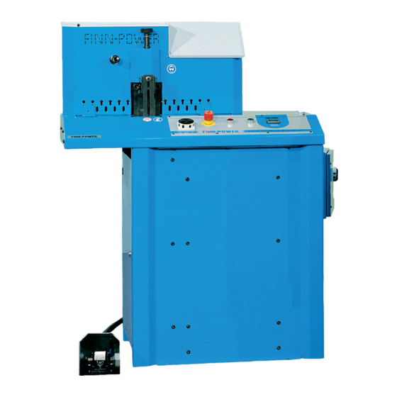
GENERAL CM75 PH is a universal hose cutting machine with capacity to cut all types and sizes of hydraulic hoses up to 2” diameter multiwire hoses. The hose is fed and measured manually. It is cut by pressing it against the rotating cutter blade. -
Page 6: Help Protect Our Environment
HELP PROTECT OUR ENVIRONMENT Disposal of the packing material The transport and protective packing is mostly manufactured from the recycled or recyclable materials. Please check local environmental regulations before disposing of packing materials. Rather than throwing these materials away, please take them to your community recycling centre. Disposal of your old machine Old machines contain materials which can be recycled. -
Page 7: Warnings
WARNINGS General The machine is intended for professional use. It is to be operated only by a trained operator who has understood the dangers involved in the operation. The rotating cutter blade is guarded by guard plates mounted on the cutting point. In neutral position when the foot pedal is not pressed, touching the blade has been prevented so that the pusher for making the cutting movement is in the upper position, thus prohibiting the guard plates from dropping down. -
Page 8: Danger Zones
WARNING 4 WATCH OUTFOR THE ROTATING MOTOR AND BLADE! WARNING 5 High voltage! The electric box is to be opened only by a professional electrician! WATCH OUT FOR THE SPARKING AND FLYING ITEMS! Danger zones... -
Page 9: Commissioning
COMMISSIONING Electrical connection CAUTION! Check that the machine voltage (see type plate) is equal to your supply voltage. For proper installation to local code, consult a licensed contractor. Tighten the cable clamp. Connect the phase conductors to the respective L1, L2 and L3 terminals in the junction box. Connect the earth connection to the ground terminal. -
Page 10: Operation
OPERATION Control identification Supply disconnecting device separates the machine from power supply. However the device itself can be made dead only by disconnecting the plug or supply cable from the mains. 1.1. Push-buttons for starting and stopping the motor. 1.2. Emergency stop button for turning off the current immediately and emptying the compressed air system. -
Page 11: Control Identification R2
Control identification R2 (OPTION) Supply disconnecting device separates the machine from power supply. However the device itself can be made dead only by disconnecting the plug or supply cable from the mains. 1.1. Push-buttons for starting and stopping the motor. 1.2. -
Page 12: Covers
Covers PLATES When the pusher is in upper position, the springing guard plates on both sides of the blade are in horizontal position and cannot drop down and let the blade come into view. When a hose is being cut, the plates drop down, thus enabling cutting. -
Page 13: Hose Cutting
Hose cutting DO NOT KEEP YOUR HANDS TOO CLOSE TO THE CUTTING POINT! USE EYE SHIELDS! • Place the hose to the cutting point as indicated in the figure (1). • Use the adjusting shaft (2) to adjust the pusher height so that the free motion of the pusher remains minimal: lower for small hoses and upper for large ones. -
Page 14: Tightening Of Vbelts
Tightening of V belts • Open the door on the right. • Loosen the two M12 locking screws on the motor base plate (7) (see picture, page 7). • Loosen the locking nut from the clamping screw (2). Turn the screw clockwise, and the belts tighten. -
Page 15: Guarantee
Working and travelling costs as well as freight charges caused by guarantee repairs are not covered by the guarantee. Guarantee repairs shall be carried out at Lillbacka Powerco Oy, Alahärmä, Finland, or by an authorized Finn- Power service. In case guarantee repair is demanded, the customer has to prove that the machine is under guarantee. -
Page 16: Technical Data
Technical data CM75 PH Capacity 2” Electric motor 7.5 kW Cutter blade Ø 520 x 4 mm, centre hole Ø 38 mm Speed of blade rotation 2840 rpm Sound pressure level 82 dB(A) during hose cutting, 74.9 dB(A) idle speed Frequency 50 Hz Motor power Voltage V / Current A / Fuse A...
Need help?
Do you have a question about the FINN POWER CM75PH and is the answer not in the manual?
Questions and answers