Table of Contents
Advertisement
Lillbacka Powerco Oy
P.O.B. 1
FIN-62301 Härmä, Finland
tel. + 358 6 485 4444
fax + 358 6 485 4400
OPERATING
INSTRUCTIONS
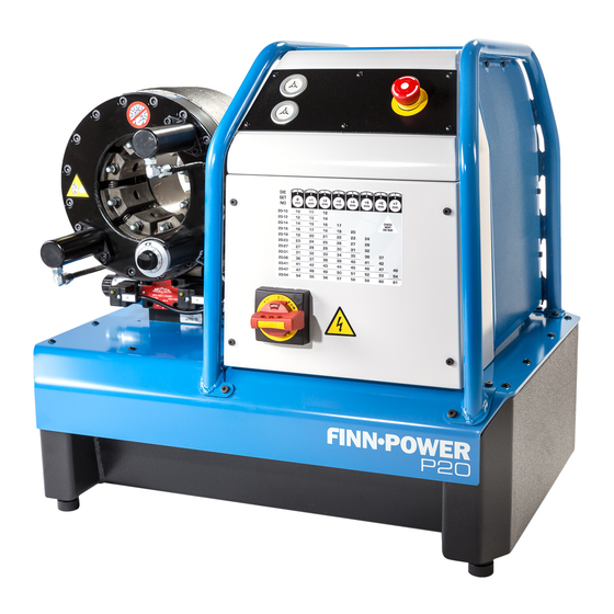
FINN-POWER
P20 MS
P20 IS/AS
P20 VS
P21 MS
P21 IS/AS
P21 VS
P32 MS
P32 IS/AS
P32 VS
P51 IS/AS
P51 VS
CC22 IS/AS
CC22 VS
MANUFACTURING YEAR
RELEASED 06/00
KEEP THIS MANUAL FOR FUTURE NEEDS
THE MACHINE HAS BEEN DESIGNED FOR CRIMPING HOSE FITTINGS.
LILLBACKA POWERCO SHALL NOT BE HELD LIABLE FOR ANY
PRODUCT WHICH HAS BEEN CRIMPED ON THE MACHINE. THE
MACHINE
HAS
BEEN
TEMPERATURE, IN DRY INDOOR CONDITIONS AND IN SUFFICIENT
ILLUMINATION. USING THE MACHINE FOR ANY OTHER PURPOSE IS
NOT ALLOWED WITHOUT WRITTEN CONSENT FROM THE FACTORY.
¨
¨
¨
¨
¨
¨
¨
¨
¨
¨
¨
¨
¨
____________
DESIGNED
TO
OPERATE
IN
ROOM
Advertisement
Table of Contents

Related Manuals for Lillbacka Powerco FINN-POWER P20 MS


Summary of Contents for Lillbacka Powerco FINN-POWER P20 MS
- Page 1 MANUFACTURING YEAR ____________ RELEASED 06/00 KEEP THIS MANUAL FOR FUTURE NEEDS THE MACHINE HAS BEEN DESIGNED FOR CRIMPING HOSE FITTINGS. LILLBACKA POWERCO SHALL NOT BE HELD LIABLE FOR ANY PRODUCT WHICH HAS BEEN CRIMPED ON THE MACHINE. THE MACHINE BEEN DESIGNED...
-
Page 2: Table Of Contents
CONTENTS CONTENTS ........................... 2 GENERAL ..........................3 TRANSPORT ..............................3 STORAGE ................................3 MOUNTING ................................. 3 WARNINGS ........................... 4 GENERAL ................................4 DANGER ZONES..............................4 COMMISSIONING ......................... 5 OIL FILL ................................5 ELECTRICAL CONNECTION ..........................5 QUICK FIX-PACKAGE ............................5 OPERATION.......................... -
Page 3: General
GENERAL FINN-POWER crimping machines are electrically operated hydraulic crimping machines for hydraulic hose assemblies. The crimping machine comprises a crimping head and a hydraulic unit mounted on the oil tank which serves as machine frame. FINN-POWER crimping machine is normally delivered with a 3-phase electric motor. On request it can be equipped with a single phase motor. -
Page 4: Warnings
WARNINGS General The machine is intended for professional use. It is to be operated only by a trained operator who has understood the dangers involved in the operation. Openings between the dies exceed 6 mm, thus being large enough to let fingers go between the dies and get crimped. -
Page 5: Commissioning
WARNING 5 (P32 model) The rear of the crimping head is covered by a housing protecting the operator from the crimping hazard under the housing between rear flange and cylinder. Do not remove this housing! keeptool.eps WARNING 6 When changing dies with the quick change tool, hold the handle as shown in the above figures. -
Page 6: Operation
OPERATION Control identification MS -control 1. Supply disconnecting device for starting and stopping the motor. The device is used to separate machine from power supply. However, the undervoltage trip can be made dead only by disconnecting the plug or supply cable from the mains. -
Page 7: Control Panel Is/As
Control panel IS/AS TRIP P20aepan.eps 1. SUPPLY DISCONNECTING DEVICE The supply disconnecting device starts and stops the motor. It is used to disconnect the machine from power supply. However, the undervoltage trip can be made dead only by disconnecting the plug or supply cable from the mains. - Page 8 AUTOMATIC : Crimping movement gets started when the fitting is pressed against the stop device. The movement stops if the stop device is not adequately pressed by the fitting. It can also be stopped by withdrawing the fitting from the stop device before it is gripped by dies. If need be, dies can be opened by using retraction button 7.
-
Page 9: Control Panel Vs
Control panel VS 25.4 32-22 0.01 28.4 CONNECTOR 1 P20vs.eps 1. SUPPLY DISCONNECTING DEVICE The supply disconnecting device starts and stops the motor. It is used to disconnect the machine from power supply. However, the undervoltage trip can be made dead only by disconnecting the plug or supply cable from the mains. - Page 10 5. CRIMPING BUTTON The dies will close when this button is pressed. The dies move until the button is released or the set crimping diameter has been reached. When using this button, manual mode must be selected. 6. RETRACTION BUTTON The dies will open when this button is pressed.
-
Page 11: Covers P32
17. MODE SELECTION See VS control, page 9. MANUAL : Master dies can be opened by pressing retraction button 6 and closed by pressing crimping button 5. Manual mode is used when changing dies and adjusting settings. Ees-taas.wmf SEMI-AUTOMATIC : Crimping movement gets started when the semi-automatic button 4 is pressed. The movement can be interrupted by releasing the button. -
Page 12: Selecting The Die Set P20, P21
Selecting the die set P20, P21 Use only original Finn-Power die sets in Finn-Power crimping machines. Refer to the fitting manufacturer's specifications for proper crimping diameter for the fitting. Each die set has its own crimping range. Follow it to assure the roundest possible crimping result. The minimum crimping diameter D is marked on each die set. -
Page 13: Selecting The Die Set P32
Selecting the die set P32 Use only original Finn-Power die sets in Finn-Power crimping machines. Refer to the fitting manufacturer's specifications for proper crimping diameter for the fitting. Each die set has its own crimping range. Follow it to assure the roundest possible crimping result. The minimum crimping diameter D is marked on each die set. -
Page 14: Fp140 Die Sets For P51 -Model
FP140 DIE SETS FOR P51 -MODEL FP140 die sets for large fittings are attached directly to the master dies. FP140 die sets are manufactured with following dimensions: Die set No Crimping range 18860/84 84 ... 92 mm 18860/92 92 ... 100 mm 18860/100 100 ... -
Page 15: Quick Change Vs
QUICK CHANGE VS (OPTION) An optional Quick Change Tool Base enables storing die sets under the machine. Die sets can be installed into the master dies with a quick change tool one set at a time. • Before installing dies, make sure that the master dies are clean. •... -
Page 16: Setting The Crimping Diameter Ms
Setting the crimping diameter MS From crimping diameter chart on the electric box door you can see the die set numbers and the corresponding crimping ranges. The upper section of the chart shows the corresponding dial position for each crimping diameter in the columns. -
Page 17: Setting The Crimping Diameter Is/As
Setting the crimping diameter IS/AS From the crimping diameter chart on the electric box door you can see the die set numbers cor- responding crimping ranges. The upper section of the chart shows cor- responding dial position for each crimping diameter in the columns. -
Page 18: Setting The Crimping Diameter Vs
Setting the crimping diameter VS • While the crimping diameter display is surrounded by the cursor, activate it by pressing E. • Select the desired crimping diameter by turning the selector and press E. • Check the die set used and change it if need be. •... -
Page 19: Crimping Is/As/Vs -Controls
Crimping IS/AS/VS -controls WHEN CRIMPING A FITTING, HOLD THE HOSE FAR ENOUGH TO AVOID CRIMPING YOUR HAND ! MANUAL MODE ees-taas.wmf Manual mode is used during die set change, set-up and test run. 1. Select MANUAL MODE. 1. Press the start button. 2. -
Page 20: Adjustment Of Retraction Diameter Is/As
20stopp.jpg p50stop.hgl P20, P21 and P32 -models CC22 and P51 -models 5. P20, P21 and P32 –models: Loosen the locking nut (3) and push the stop device (4) against the fitting so that the spring-loaded stop device is compressed, making the limit switch inside it actuate. Tighten the locking nut. -
Page 21: If The Machine Does Not Work
If the machine does not work... • Make sure the supply disconnecting device is in position 1. • Check that the plug is in the socket. • MS –model: If the motor is running but the machine does not crimp, check that the crimping diameter dial is plugged in. -
Page 22: Greasing Cc22
Greasing CC22 Fig. 1 Fig. 2 • Open the dies to maximum retraction. • Lubricate the surfaces daily with pressure-proof grease like Molub Alloy OG-H or equivalent. • Lubricate the front side of the die through the grease nipples using a compressor gun (see fig. 2). •... -
Page 23: Filter Change P51
Filter change P51 • Open the covering plate in the tank cover. • Unscrew the filter insert and remove it. • Handle the old filter according to law. • Lubricate the seal of the new filter insert with hydraulic oil. •... -
Page 24: Troubleshooting
Working and travelling costs as well as freight charges caused by guarantee repairs are not covered by the guarantee. Guarantee repairs shall be carried out at Lillbacka Powerco Oy, Alahärmä, Finland, or by an authorized Finn-Power service. In case guarantee repair is demanded, the customer has to prove that the machine is under guarantee. -
Page 25: Technical Data
TECHNICAL DATA Technical data P20 3-phase 1-phase Capacity 1 ½ 1 ½ Crimping diameter range *) Ø (mm) 4...61 4...61 Max opening Pump l/min Max pressure Crimping force 1370 1370 Theoretical production capacity per hour Sound pressure level dB(A) Enclosure class IP 54 IP 54 Closing speed of master dies... - Page 26 READ THE INSTRUCTIONS THOROUGHLY TO SECURE SAFE AND CORRECT OPERATION OF THE MACHINE.
-
Page 27: Technical Data P21
Technical data P21 3-phase 1-phase Capacity 1 ½ 1 ½ Crimping diameter range *) Ø (mm) 4...61 4...61 Max opening Pump l/min Max pressure Crimping force 1370 1370 Theoretical production capacity per hour Sound pressure level dB(A) Enclosure class IP 54 IP 54 Closing speed of master dies mm/s... - Page 28 READ THE INSTRUCTIONS THOROUGHLY TO SECURE SAFE AND CORRECT OPERATION OF THE MACHINE.
-
Page 29: Technical Data P32
Technical data P32 3-phase 1-phase Capacity Crimping diameter range *) Ø (mm) 4...87 4...87 Max opening Pump l/min Max pressure Crimping force 2000 2000 Theoretical production capacity per hour Sound pressure level dB(A) Enclosure class IP 54 IP 54 Closing speed of master dies mm/s Frequency 50 Hz Motor power... -
Page 30: Technical Data P51
READ THE INSTRUCTIONS THOROUGHLY TO SECURE SAFE AND CORRECT OPERATION OF THE MACHINE. Technical data P51 3-phase Capacity 2 ½ (industrial hose 4”) Crimping diameter range *) Ø (mm) 4..120 Max opening Pump l/min 18/6 Max pressure Crimping force 2800 Theoretical production capacity per hour Sound pressure level... - Page 31 Weight 260 kg, excluding oil. READ THE INSTRUCTIONS THOROUGHLY TO SECURE SAFE AND CORRECT OPERATION OF THE MACHINE. P50mit.hgl...
-
Page 32: Technical Data Cc22
Technical data CC22 3-phase 1-phase Capacity 1 ¼ 1 ¼ Crimping diameter range *) Ø (mm) 4...54 4...54 Max opening Pump l/min Max pressure Crimping force Theoretical production capacity per hour 1700 Sound pressure level dB(A) Enclosure class IP 54 IP 54 Closing speed of master dies mm/s... - Page 33 READ THE INSTRUCTIONS THOROUGHLY TO SECURE SAFE AND CORRECT OPERATION OF THE MACHINE.
Need help?
Do you have a question about the FINN-POWER P20 MS and is the answer not in the manual?
Questions and answers