
Related Manuals for Toshiba T300BMV2


Summary of Contents for Toshiba T300BMV2
- Page 1 T300BMV2 MEDIUM VOLTAGE ADJUSTABLE SPEED MOTOR DRIVE NSTRUCTION ANUAL TOSHIBA INTERNATIONAL CORPORATION Document Number: IF08CZ9 September 2019 Toshiba Reference File #328...
- Page 2 TOSHIBA INTERNATIONAL CORPORATION 13131 WEST LITTLE YORK HOUSTON, TEXAS 77041 Tel: 1-713-466-0277 1-800-231-1412 Printed in U.S.A. - ii - IF08CZ9 September, 2019 Toshiba Reference File #328...
- Page 3 Adjustable Speed Drive Please complete the Warranty Card supplied with the ASD and return it to Toshiba by prepaid mail. This will activate the 12 month warranty from the date of installation; but, shall not exceed 18 months from the date of purchase.
- Page 4 TOSHIBA is a registered trademark of the Toshiba Corporation. All other product or trade references appearing in this manual are registered trademarks of their respective owners.
- Page 5 CAUTION The word CAUTION without the safety alert symbol indicates a potentially hazardous situation exists which, if not avoided, may result in equipment and property damage. CAUTION - v - IF08CZ9 September, 2019 Toshiba Reference File #328...
- Page 6 Arc Flash Hazard Symbol A symbol which indicates a hazard of injury from arc flash. It is comprised of an equilateral triangle enclosing an arc flash image. - vi - IF08CZ9 September, 2019 Toshiba Reference File #328...
- Page 7 If the labels are damaged or if additional labels are required, contact your Toshiba representative for additional labels. Labels attached to the equipment are there to provide useful information or to indicate an imminently hazardous situation that may result in serious injury, severe property and equipment damage, or death if the instructions are not followed.
- Page 8 Be Provided With The Current Limiting Fuses Indicated On The Drive Namplate. The Remote Input Controller Must Be Electrically Interlocked To The Drive As Indicated In The Drive Drawings. PC94060P296 - viii - IF08CZ9 September, 2019 Toshiba Reference File #328...
- Page 9 Complete rating data is also provided on the rating sheet included in the supplementary drawing packet. Ensure that all rating data matches the power system and the driven load connected to the equipment. - ix - IF08CZ9 September, 2019 Toshiba Reference File #328...
- Page 10 INFORMATION labels that will be found on the equipment are shown below: Torque Label Service Label LISTED UL Label (for UL Listed drives) CE Label (for drives designed for use in the European Union) - x - IF08CZ9 September, 2019 Toshiba Reference File #328...
- Page 11 • Modification of this equipment is dangerous and must not be performed except by factory trained representatives. When modifications are required contact your Toshiba representative. • Inspections may be required before and after moving installed equipment.
- Page 12 • Include any other product-specific requirements. Disposal Never dispose of electrical components via incineration. Contact your state environmental agency for details on disposal of electrical components and packaging in your area. - xii - IF08CZ9 September, 2019 Toshiba Reference File #328...
- Page 13 Safety Requirements for Employee Workplaces. Outside the U.S., applicable national and local installation safety practices should be followed. In the EU refer to section 6.5 of HD 637 and its sub clauses. - xiii - IF08CZ9 September, 2019 Toshiba Reference File #328...
- Page 14 • Turn the power on only after attaching and/or securing the front cover. • Ensure the correct phase sequence and the desired direction of motor rotation in the Bypass mode (if applicable). - xiv - IF08CZ9 September, 2019 Toshiba Reference File #328...
- Page 15 Please contact Toshiba for application-specific information and for training support. • The Toshiba ASD is part of a larger system and the safe operation of the device will depend on observing certain precautions and performing proper system integration.
- Page 16 Warning signs to this effect shall be posted at or near the hazard. • Personal protection equipment shall be provided and used to protect employees from any hazards inherent to system operation. - xvi - IF08CZ9 September, 2019 Toshiba Reference File #328...
- Page 17 • The operating controls and system status indicators should be clearly readable and positioned where the operator can see them without obstruction. • Additional warnings and notifications shall be posted at the equipment installation location as deemed required by Qualified Personnel. - xvii - IF08CZ9 September, 2019 Toshiba Reference File #328...
- Page 18 Wait for at least the minimum time indicated on the label and ensure that the Charge LED has gone out before opening the door of the ASD once the ASD power has been turned off. • Do Not attempt to disassemble, modify, or repair the ASD. Call your Toshiba sales representative for repair information.
- Page 19 This page intentionally left blank. - xix - IF08CZ9 September, 2019 Toshiba Reference File #328...
-
Page 20: Table Of Contents
CIRCUIT OPERATION ....................32 Main Circuit Configuration ..................32 Control ........................34 Vector Control Block Diagram ................... 34 V/f Control Block Diagram ..................34 Speed Reference....................... 35 Vector Control Speed Control ..................36 - xx - IF08CZ9 September, 2019 Toshiba Reference File #328... - Page 21 Frame BS4 drive lifting and assembly ............... 55 Frame C4 drive lifting and assembly ................. 56 Frame C4 drive main cable installation ..............57 Frame C4 module lifting .................... 58 Frame C4 4160V module installation ................. 59 - xxi - IF08CZ9 September, 2019 Toshiba Reference File #328...
-
Page 22: Introduction
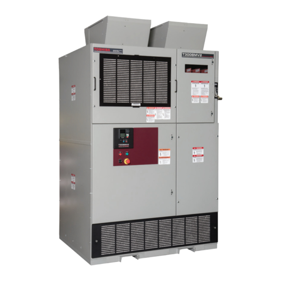
INTRODUCTION Thank you for purchasing the T300BMV2 Medium Voltage ASD. This adjustable frequency, solid- state AC drive features a 3φ input isolation transformer with a 24-pulse converter design, a 32-bit CPU, and a three-unit power module inverter section providing a 5 level output for 4160V drives. These drives also feature as standard, an 8 key Control Panel with a LCD screen and 2 discrete LED lamps to indicate Ready, Run, Local, Remote and Alarm/Fault. -
Page 23: Initial Commissioning
This assures correct operation, of the equipment, for reasons with reliability and safety performance. It is important to make arrangements for such a check and that sufficient time is allowed for it. - 2 - IF08CZ9 September, 2019 Toshiba Reference File #328... -
Page 24: Cautions On Changing Setting Parameters
If such an error occurs, the settings must be reloaded from a saved file. If no setting file exists, the drive must be re-commissioned. Do not turn off the control power supply, under any circumstances, while writing data to the EEPROM. - 3 - IF08CZ9 September, 2019 Toshiba Reference File #328... -
Page 25: Inspections And Maintenance
As a basic rule, cleaning should start from the upper parts and end at the lower parts. Cleaning of the lower parts last will allow proper removal of substances that could drop from the upper parts. - 4 - IF08CZ9 September, 2019 Toshiba Reference File #328... -
Page 26: Main Components
Note that the anti-static coating is only on the inner side of the bag. 5) Check the protection functions for proper operation (Door switches, OH, E-stop...) 6) Check the insulation resistance of the medium voltage circuits. - 5 - IF08CZ9 September, 2019 Toshiba Reference File #328... -
Page 27: Recommended Parts To Be Regularly Renewed
Contact Toshiba for Capacitors replacement of these devices On Circuit Boards Oil-filled capacitor 20 years Main circuit Control power supply 7 years Fuse Main circuit 7 years Control circuit 7 years - 6 - IF08CZ9 September, 2019 Toshiba Reference File #328... -
Page 28: Recommended Spare Parts
This is a general list of spares. Check the specific job drawings for other components that may need to be spared. *** It is recommended that failed power modules be replaced as a unit and that the failed modules be returned to Toshiba for repair and testing. - 7 - IF08CZ9 September, 2019... -
Page 29: Preparations For Inspection And Maintenance Of Equipment (Powering-Off)
Note! A meter rated for the main circuit voltage is required to safely check the main circuit voltages. Grounding 8) Ground the 3-phase input power supply terminal at the main circuit input terminals. Work 9) Perform the necessary maintenance. - 8 - IF08CZ9 September, 2019 Toshiba Reference File #328... -
Page 30: Recovery After Inspection And Maintenance Of Equipment (Powering-On)
Press the interlock switch on the operation panel (See Fig. 1 in the next section). operation of (When the LED is turned off, the interlock is off. If the drive is ready, it equipment will start if commanded).) - 9 - IF08CZ9 September, 2019 Toshiba Reference File #328... -
Page 31: Overview
OVERVIEW Display/Keypad (EOI) The following figure shows the display/keypad of the equipment. Refer to the keypad operation manual for more details on its use. EOI Diagram Figure 1. - 10 - IF08CZ9 September, 2019 Toshiba Reference File #328... - Page 32 Operating the INTERLOCK pushbutton will result in an inverter gate block and free-run deceleration of the load. - 11 - IF08CZ9 September, 2019 Toshiba Reference File #328...
-
Page 33: How To Handle Faults
Light Emitting Diode MCCB Molded Case Circuit Breaker Power electronics Processor for Various Inverter control Integration (VII=7). Toshiba dedicated power electronics control 32-bit micro-controller. Switching power supply that providing ±15 VDC and +5 VDC for boards. Random Access Memory Initialize Act of initialization. -
Page 34: General Specifications (Structure)
Paint color Cubicle ANSI 61 Gray Consult factory for surface optional colors Cubicle structure Front maintenance Cubicle protective NEMA 1, Forced ventilated structure With channel base Air filter Front mounted - 13 - IF08CZ9 September, 2019 Toshiba Reference File #328... -
Page 35: Altitude And Temperature De-Rating
(1) Older motors, or motors with marginal insulation systems, may require filters to help reduce the stress on the insulation system. Consult Toshiba application engineering. (2) Exceeding the peak voltage and allowable voltage rise time of the motor insulation system will reduce motor life expectancy. -
Page 36: General Specifications (Electrical)
Cabinet internal light Typical operating LpAm (Operator) 78 dBA sound levels LpAm (Bystander) 78 dBA measured at a LpC (Operator) 79 dBC distance of 1m x 1.5m high - 15 - IF08CZ9 September, 2019 Toshiba Reference File #328... -
Page 37: General Specifications (Control)
128x64 Pixel Graphical LCD display Operation apparatus Backlit type interlock switch: 1 Unlit reset switch: 1 Operation via 8 key keypad and a 15pulse/30detent incremental encoder Connector Personal computer connection Ethernet modular jack - 16 - IF08CZ9 September, 2019 Toshiba Reference File #328... - Page 38 Remarks Analog signal output 10VDC x 1 Channel on XIO brd. Connected measuring equipment must be isolated from ground Analog signal input T300BMV2: Connected 10VDC x 1 channel on XIO brd. source equipment must be isolated from ground Digital input...
- Page 39 Rating Specifications NEMA Type 1 Standard Ratings Table (T300BMV2) Motor Output Output Output Current Overload Current Standard Input Output Voltage 100% 110~115%-60 s. Frame Model Voltage & Frequency MB4AAN44030 AAA0 4160V A4µ 0~4160 V MB4AAN44035 AAA0 A4µ 0~75 Hz MB4AAN44040 AAA0 A4µ...
-
Page 40: Protective Functions
Power Module overheat OH_T_x Input Rectifier Overheat OH_REC Transformer over heat OH_TR AC Link Reactor Overheat OH_ACL_T Hardware Software Start Item Abbreviation Heavy Fault Medium Light Detection Detection Interlock Fault Fault - 19 - IF08CZ9 September, 2019 Toshiba Reference File #328... -
Page 41: General Cubicle Structure
"*" indicates that the equipment outputs the trip signal to the input main circuit breaker. “x” indicates the phase (U,V,W). General Cubicle Structure The configuration and dimensions of the equipment are described below. - 20 - IF08CZ9 September, 2019 Toshiba Reference File #328... -
Page 42: Cubicle Structure And Dimensions
3) Provide a clearance of at least 24 inches (610 mm) above the exhaust fans. 4) The following are not included in the dimensions on the next page: a) Handle projections b) Door mounted device projections c) Fastener projections - 21 - IF08CZ9 September, 2019 Toshiba Reference File #328... -
Page 43: Dimensions And Weights Of Equipment
MB4BAN44100-200AAA0 4160 11.6 (295) 30.2 (767) 31.6 (803) 260 (118) MB4BSAN44100-200AAA0 4160 11.6 (295) 30.2 (767) 31.6 (803) 260 (118) MB4CAN44225-300AAA0 4160 16.7 (424) 35.4 (899) 38.6 (980) 400 (181) - 22 - IF08CZ9 September, 2019 Toshiba Reference File #328... -
Page 44: Interface
Grounding must follow local and national codes by attaching a properly sized ground conductor to the drive equipment. Recommended Ground Circuit Speed Sensor Motor Input transformer Primary Secondary Inverter main circuit Control Ground Drive Power/Chassis Ground Earth Ground Grounding - 23 - IF08CZ9 September, 2019 Toshiba Reference File #328... -
Page 45: Motor Interface
There are three PLG types, a differential type, a single-end totem pole type, and a single-end open collector type. The connections to the PLG, the jumper setting of XIO brd., and the parameter settings for each PLG are different. - 24 - IF08CZ9 September, 2019 Toshiba Reference File #328... -
Page 46: Pulse Signal Output
PG with a marker pulse is used. These pulse signals, at the level of the power supplied from an outside source, are isolated from the control power supply of the drive, through photo-couplers. Pulse Output Circuit - 25 - IF08CZ9 September, 2019 Toshiba Reference File #328... - Page 47 MP_CW_TM_H1_ MP_BR09_CL MP_BH_RL_A_ SEL_MRH MP_OLU_LFD_ MP_BR10_CL MP_BH_RL_TR_ MP_OLU_HFD_ MP_WLK1_ MP_GP_RL_TR_ IM_NUM_B1 MP_OLU_HPL_N MP_CF_IL_ N.U. IM_NUM_B0 EXT0 MP_OLU_LPL_N MP_SPH_IL_ N.U. XFR_CHK QSTOP MP_SPH_ON MP_OL_P_IL_ N.U. MP_SPH_MCC_F_ N.U. N.U. MP_SW_TM_H_ N.U. N.U. - 26 - IF08CZ9 September, 2019 Toshiba Reference File #328...
- Page 48 External interlock 0: Operation permitted 1: Operation permitted External interlock Off while running; causes a deceleration stop. IM_NUM_B0 Motor unit count switch bit 0 IM_NUM_B1 Motor unit count switch bit 1 - 27 - IF08CZ9 September, 2019 Toshiba Reference File #328...
- Page 49 0:Flow Low MP_GP_RL_TR_ SuddenGasPressRyTrip 0:Trip MP_OL_LVL_A_ OilLevelAlarm 0:Alarm MP_OL_LVL_TR_ OilLevelTrip 0:Trip MP_OL_P_IL_ OilLubPump I/L SW 0:Interlocked MP_OL_TM_A_ OilTemperatureAlarm 0:Alarm MP_OL_TM_TR_ OilTemperatureTrip 0:Trip MP_OLU_HFD_ OilLubricationUniHFD 0:Fault MP_OLU_HPL_N OilLubUHiPressLineN 1:Normal MP_OLU_LFD_ OilLubricationUniLFD 0:Alarm - 28 - IF08CZ9 September, 2019 Toshiba Reference File #328...
- Page 50 One shot to stop (SEL=1) External safety switch Operation enabled when 1 “**” The function of many operation signals can be reversed via sign bit settings if needed. INTERFACE (cont’d) - 29 - IF08CZ9 September, 2019 Toshiba Reference File #328...
-
Page 51: Digital Output
The following figure shows the input circuit: XIO, ARND-4045 AIN1_TYPE=0 +/-10V JP1B Input TB2-1 AIN1_TYPE=1 AIN1 Gain Data destination AIN1_GS AIN1_AS TB2-2 AIN1_TYPE=2 4-20mA JP1A 4-20mA Input Offset AIN1_OS Analog Input Circuit - 30 - IF08CZ9 September, 2019 Toshiba Reference File #328... - Page 52 AIN1_GS = 2 / (20mA - 4mA) x 20mA = 2.5 AIN1_OS = -2.5 x 4mA / 20mA = -0.5 AIN1_AS = SP_REF_AIN1 AIN1_TYPE - 31 - IF08CZ9 September, 2019 Toshiba Reference File #328...
-
Page 53: Analog Output
The output of the rectifiers is connected to three inverter power modules that produce 3-phase AC power at the frequency and voltage required by the motor. Configuration - 32 - IF08CZ9 September, 2019 Toshiba Reference File #328... - Page 54 This is shown in the output waveform below. This produces a sine wave motor current with low distortion. Generation of High Voltage by Wye Connection 2400V 4160V Motor 1 phase inverter Output Voltage and Current Waveforms - 33 - IF08CZ9 September, 2019 Toshiba Reference File #328...
-
Page 55: Control
Tension ld, lq Current control detection Speed detection (Option) V/f Control Block Diagram Speed Voltage Reference Reference Reference Control Id,Iq Current Detection - 34 - IF08CZ9 September, 2019 Toshiba Reference File #328... -
Page 56: Speed Reference
(2) LMT_SP_MIN LMT_SP_MIN is used as a minimum speed. The drive will run at this speed anytime the start command is on and the speed reference is less than LMT_SP_MIN. - 35 - IF08CZ9 September, 2019 Toshiba Reference File #328... -
Page 57: Vector Control Speed Control
FLG_MOT_G <Anti-overshoot> SFC (option) Simulator <Proportion> <ACR> <Inertia> <Differentiation> <Limit> SFC_DATA FLT_SFC: ACR simulator OP_SFC_P: Proportion OP_SFC_J: Inertia OP_SFC_D: Differentiation OP_SFC_A: Anti-overshoot LMT_SFC_D: Differentiation limit Speed Control CIRCUIT OPERATION (cont’d) - 36 - IF08CZ9 September, 2019 Toshiba Reference File #328... -
Page 58: Vector Control Simulator Follower Control (Sfc, Optional Control Used With A Speed Sensor)
SSEQOUT1 Bit 2 (option) longer, this status is determined as an A<=B Tension reference input asCUT detection. with gain TENS_R2 (option) EXT_TENS_GAIN Reverse coiling option command DI1_INP R_TEN Torque Reference - 37 - IF08CZ9 September, 2019 Toshiba Reference File #328... -
Page 59: Vector Control Iq Limit (Torque Current Limit)
LMT_SP_BASE Normal rotation Normal rotation IQ limit deceleration acceleration LMT_IQ_BAS LMT_IQ_TOP LMT_IQ_INV 100% Speed LMT_SP_BASE Torque limit Magnetic flux reference Inverse rotation Inverse rotation FL_R LMT_TRQ acceleration deceleration IQ Limit - 38 - IF08CZ9 September, 2019 Toshiba Reference File #328... -
Page 60: Vector Control D-Q Axis Current Control
ACR_P: P gain ACR_W1: Response IQ_REF <Integral> <Proportional> ED_R ID_R MI_ID_BASE Rated Current ID_R Adjustment ID_FUNC CS_MOTOR_CURR Modulation CS_EQUIP_CURR rate FL_R ID_FBK MA_FLUXFUNC 00 - 20 D-Q Axis Current Control - 39 - IF08CZ9 September, 2019 Toshiba Reference File #328... -
Page 61: V/F Control
FLT_FLX Overcurrent VF_CP_ILIM control VF_FLT_ILIM VF_WSCMP Slip frequency Modulation (Advancced V/f) VF_WSCMP_EN ratio Automatic CS_MOTOR_RPM Torque ED_R boost MI_ID_BASE MI_R1_SET MI_L_CMP VF_TRQBST_GAIN VF_SP_TRQBST (Simple V/f) Start torque boost VF_LSP_VBST VF_LSP_VBSTSP - 40 - IF08CZ9 September, 2019 Toshiba Reference File #328... -
Page 62: Control Circuit For Sm (Synchronous Motor) Control
Operation lowest speed MS_PLL_SW_SP LMT_SP_MIN Armature voltage MAIN_VAC_F MS_START_IQ Stator current I1_F MS_FCR_INI Field current MS_FCR_IQACC FC_FBK time Mode3 : 0PS Control Mode1 : Mode2 : Initial position detection Constant IQ Acceleration - 41 - IF08CZ9 September, 2019 Toshiba Reference File #328... -
Page 63: Sm Control Block Diagram
Voltage Current ÷ reference control SP_F FL_R $LMT_IQ_BAS $ACR_A $LMT_E IQ_FBK $LMT_IQ_TOP $ACR_P ID_FBK $LMT_IQ_INV $ACR_W1 $LMT_SP_BASE $LMT_I1 FL_CMD To Exciter FC_REF $MS_KF1 Voltage control MAIN_VAC_F ÷ $MS_FLBST_INI $MS_FLBST_IQACC $MS_FLBST_VPLL - 42 - IF08CZ9 September, 2019 Toshiba Reference File #328... -
Page 64: Speed Feedback (Option)
SP_F Speed detection Pulse count measurement Rotation direction detection θ detection CS_RES_TYPE = 1 PGB-F CS_RES_PGFLT (factory setting) CS_PGOUT = 0 CS_PGCNT = 256 (PG pulse count) PG Speed Detection - 43 - IF08CZ9 September, 2019 Toshiba Reference File #328... -
Page 65: Operation
Turn on control power supply. 480 VAC-50/60 Hz Turn on main circuit power supply. Powering-off sequence Check that operation is stopped. Turn off main circuit power supply. Turn off control power supply. 480VAC-50/60 Hz - 44 - IF08CZ9 September, 2019 Toshiba Reference File #328... -
Page 66: Pre-Operation Check Points
2) After the motor has stopped, interlock the drive with the interlock button on the keypad. 3) Turn off the external main power supply. 4) Turn off the control power supply MCCB "CONTROL." - 45 - IF08CZ9 September, 2019 Toshiba Reference File #328... -
Page 67: Data Control
Further, this information becomes an important clue to determine the cause of intermittent faults. It is important to keep a precise record. - 46 - IF08CZ9 September, 2019 Toshiba Reference File #328... -
Page 68: Repair
Cautions on Repair • Be sure to use only the renewal parts specified by Toshiba. Parts other than those specified by Toshiba may not only not demonstrate the stipulated performance but also affect the safety. If spare parts are not available, contact Toshiba to order them or ask for replacement of parts. -
Page 69: Drive Installation Drawings
Torque power connections (10-32 120VAC Supply Cable nuts) to 30 inch-lbs. Pinch area Press buttons FIG.3 USE CAUTION on inside slide surfaces to slide tray back FIG.4 PC94060P214 - 48 - IF08CZ9 September, 2019 Toshiba Reference File #328... -
Page 70: Frame A4Μ Drive Lifting And Assembly
DRIVE INSTALLATION DRAWINGS (cont’d) Frame A4µ drive lifting and assembly - 49 - IF08CZ9 September, 2019 Toshiba Reference File #328... -
Page 71: Frame A4 And As4 Module Lifting And Installation
"B". to 10-15 ft-lbs. 6. Pull slide tray out until CONTROL WIRING slides lock. COVER 7. Remove four "C" bolts CONTROL SIGNAL & 120VAC CABLES which secure module to tray. - 50 - IF08CZ9 September, 2019 Toshiba Reference File #328... -
Page 72: Frame A4 Drive Lifting And Assembly
DRIVE INSTALLATION DRAWINGS (cont’d) Frame A4 drive lifting and assembly - 51 - IF08CZ9 September, 2019 Toshiba Reference File #328... -
Page 73: Frame As4 Drive Lifting And Assembly
DRIVE INSTALLATION DRAWINGS (cont’d) Frame AS4 drive lifting and assembly - 52 - IF08CZ9 September, 2019 Toshiba Reference File #328... -
Page 74: Frame B4 & Bs4 Module Lifting And Installation
"B" bolts 9. Torque all power 4. Disconnect control signal connections (5/16-18 hdwr) CONTROL SIGNAL & cable and 120VAC supply to 10-15 ft-lbs. 120VAC CABLES cable from module. CONTROL WIRING COVER - 53 - IF08CZ9 September, 2019 Toshiba Reference File #328... -
Page 75: Frame B4 Drive Lifting And Assembly
DRIVE INSTALLATION DRAWINGS (cont’d) Frame B4 drive lifting and assembly - 54 - IF08CZ9 September, 2019 Toshiba Reference File #328... -
Page 76: Frame Bs4 Drive Lifting And Assembly
DRIVE INSTALLATION DRAWINGS (cont’d) Frame BS4 drive lifting and assembly - 55 - IF08CZ9 September, 2019 Toshiba Reference File #328... -
Page 77: Frame C4 Drive Lifting And Assembly
DRIVE INSTALLATION DRAWINGS (cont’d) Frame C4 drive lifting and assembly - 56 - IF08CZ9 September, 2019 Toshiba Reference File #328... -
Page 78: Frame C4 Drive Main Cable Installation
DRIVE INSTALLATION DRAWINGS (cont’d) Frame C4 drive main cable installation - 57 - IF08CZ9 September, 2019 Toshiba Reference File #328... -
Page 79: Frame C4 Module Lifting
2. Load or remove power module from truck GCI6723G055 using ramp assembly GCI6723G053. Lock truck to ramp by inserting truck pins into ramp holes. Set brakes on truck before carefully rolling power module up or down ramp. - 58 - IF08CZ9 September, 2019 Toshiba Reference File #328... -
Page 80: Frame C4 4160V Module Installation
4. Torque bus link power module. power module on and off of connections (5/16-18 hdwr) truck. to 10-15 ft-lbs. - 59 - IF08CZ9 September, 2019 Toshiba Reference File #328... - Page 81 TOSHIBA INTERNATIONAL CORPORATION 13131 WEST LITTLE YORK HOUSTON, TEXAS 77041 USA www.toshiba.com/tic Telephone: 713-466-0277 800-231-1412 800-527-1204 (Canada) Fax: 713-466-8773 Printed in U.S.A. - 60 - IF08CZ9 September, 2019 Toshiba Reference File #328...
Need help?
Do you have a question about the T300BMV2 and is the answer not in the manual?
Questions and answers