Table of Contents
Advertisement
Quick Links
Advertisement
Table of Contents

Related Manuals for Textron SHERMAN+REILLY Revolution Series


Summary of Contents for Textron SHERMAN+REILLY Revolution Series
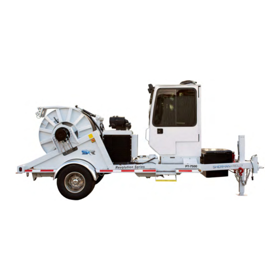
- Page 1 PT‐3500 / PT‐7500 Puller Tensioner Operators Manual...
-
Page 3: Table Of Contents
Table of Contents Section 1: Introduction Terms of Use Section 2: Specifications PT-3500 General Overview PT-3500 Key Features PT-3500 Specification Details PT-7500 General Overview PT-7500 Key Features PT-7500 Specification Details Section 3: Safety Hazard Overview Safety Warning Terms General Warnings Operator Safety Precautions Employer Safety Precautions Chemical Safety... - Page 4 Section 5: Troubleshooting Quick Tips Troubleshooting Guide for Fault Codes Torque Ratings for Machine Fasteners Fuse/Relay Block Diagram Fuse/Relay Wiring Schematic PT Trailer Wiring Schematic PT Hydraulic Schematic Section 6: Maintenance Safety and Reliability Disclaimer Safety Safety Warning Terms General Care and Inspections Instructions Cleaning Fault and Malfunction Detection Hydraulic System...
- Page 5 Section 7: Service & Repair Equipment Information Major Fault Issues When to Send for Service or Repair? Section 8: Parts Sherman+Reilly Accessories Miscellaneous Replacement Parts Appendix A: Manufacturer Manuals Kubota V3800TB Engine Manual Kubota V1505T Engine Manual Dexter 10,000 lbs. Axle Manual...
-
Page 7: Section 1: Introduction
Introduction This manual is provided to assist operators and owners with the functions and proper methods for safely and efficiently getting the most from this Sherman-Reilly equipment. It is very important that every machine be operated in a safe manner. Precautions to guard against the possibility of an accident are a prerequisite to operating any type of equipment. -
Page 8: Terms Of Use
Introduction Terms of Use Publication of this manual and the safety precautions in it does not in any way represent an all-inclusive list and should not be interpreted as an all-inclusive comprehensive list of precautions and procedures. ke sure the machine is operated in accordance with all state and local safety requirements and codes, including all applicable OSHA- (Occupational Safety and Health Administration) and EPA- (Environmental Protection Agency) regulations, as well as ANSI- (American National Standards Institute) accredited standards. -
Page 10: Section 2: Specifications
Specifications PT-3500 General Overview Sherman+Reilly Revolution Series PT-3500 Single Drum Puller/Tensioner is a multi-purpose puller and tensioner capable of pulling up to 3,500 lbs., with additional re-conductoring capabilities. This distribution class puller utilizes an automatic horizontal floating levelwind that permits overhead rope retrieval with precision control. The PT-3500 is equipped with an ACG (advanced control group), allowing for a single operator at a protected central console to control payout speed, pulling speed and tension, levelwind controls, and jack position. - Page 11 Specifications Specifications Details: PT-3500 (Dimensions, weights, and capacities listed are approximate. All specifications are subject to change without notice.) Pulling Capacity TOD: 3,500 lbs., (Rated at the top of drum) Max: 4,500 lbs., (Rated maximum) Average Line Speed Pulling: 4 mph / Payout: 10 mph Maximum Conductor Reel Size 66 in.
-
Page 12: Pt-7500 General Overview
Specifications PT-7500 General Overview The Sherman+Reilly Revolution Series PT-7500 Single Drum Puller/Tensioner is a multi-purpose puller and tensioner capable of pulling up to 7,500 lbs., with additional re-conductoring capabilities. This distribution class puller utilizes an automatic horizontal floating levelwind that permits overhead rope retrieval with precision control. - Page 13 Specifications Specifications Details: PT-7500 (Dimensions, weights, and capacities listed are approximate. All specifications are subject to change without notice.) Maximum Pulling Capacity 7,500 lbs.- (Rated from top of drum to core) Average Line Speed Pulling: 4 mph / Payout: 10 mph Maximum Conductor Reel Size 66 in.
-
Page 14: Section 3: Safety
Safety Hazard Overview Please pay attention to all safety warning labels and information placards posted on the machine, components, and trailer assembly. These labels and placards are provided to assist in identifying areas containing potential hazards while also providing information regarding equipment specification and limitations. -
Page 15: General Warnings
Safety General Warnings WARNING: Batteries produce explosive WARNING: Ear protection should be gases, contain corrosive acid, and supply worn when operating machines with levels of electrical current high enough to operator ear noise levels above 85dB. cause burns. WARNING: This machine must not be used as a winch for pulling another WARNING: To prevent serious injury vehicle. -
Page 16: Operator Safety Precautions
Never use hands to check for hydraulic system Safety leaks. Hydraulic fluid escaping under pressure can cause personal injury. Operator Safety Precautions Avoid contact with pumps, cylinders, hoses, engine components, and exhaust system. Do not place any part of the body into a potential pinch point. -
Page 17: Employer Safety Precautions
Safety , and who are competent in (provided in English only) the use of overhead pulling and tensioning Employer Safety Precautions machines; to include all applicable laws, regulations, and safety standards, should be allowed to operate this machine. There are This guideline intended... -
Page 18: Chemical Safety
Safety Chemical Safety Exposure to chemicals during normal operation of the machine is limited; however, chemical exposure may be encountered through preventive maintenance and repair. Operators and maintenance/service personnel should take appropriate precautions, to include wearing all (PPE)- Personal Protection Equipment, prior to the operation, maintenance, or service of the machine. All for OEM chemicals present upon initial manufacture/shipment of machine can be made available upon request to Sherman+Reilly. -
Page 19: Section 4: Operation
Operation Terms You Need to Know Pintle Hitch Hydraulic Pump Levelwind Head Safety Chains Hydraulic Drive Motor(s) Tool Box Safety Breakaway Switch Emergency Manual Override Fire Extinguisher Safe- Rear/Nose Jack Level Gauge Diesel Fuel Tank Side [L/R] Jacks (2) Battery Hydraulic Tank w/Filter Drum/Reel Grounding Bracket (4) -
Page 20: Safe-Zone Cab
Operation Safe-Zone Cab The Safe-Zone Cab is designed to keep the operator off the ground while the equipment is in use, and is built with a polycarbonate front window, fully adjustable ergonomic seat, high-resolution color LCD screen, and a full set of electronic controls. The Safe-Zone Cab comes in several sizes and forms, dependent upon the machine. - Page 21 Operation Safe-Zone Cab Climate Control System The PT-Series Safe- control system providing customized air temperature controls for both heating and cooling. The climate control system has multiple air fan speeds- [OFF, LO, MED, HI], with overhead and foot level multidirectional vents.
-
Page 22: Operator Controls
Operation Operator Controls ReGen Icon (PT-3500) Revolution Series PT-3500 / PT-7500 Puller Tensioner Page 20... - Page 23 Operation Operator Controls **For control locations see Operator Control Panel Section on page 20. Master Power Key Switch Exterior Work Lighting Power Switch This switch is used to control This control switch, located power operator on the door panel, operates in controls.
-
Page 24: System Control Panel
Operation Operator Controls **For control locations see Operator Control Panel Section on page 20. Rotational Control Knob/Button System Control Panel This knob, when rotated, system controls the value of a control panel selected variable field on the has 15 soft key display. - Page 25 Operation Operator Controls **For control locations see Operator Control Panel Engine Control Display Section on page 20. The engine control display shows general system and operation specific information. System Control Panel The PT-3500 is equipped with a Tier 4 Final SELECT MODE diesel engine that requires periodic cleaning / Push and Hold the [SELECT MODE] button for...
- Page 26 PT-3500 TIER 4 ENGINE Any time the lamp begins flashing, the operator Diesel Particulate Filter (DPF) and REGEN should increase the loading on the engine so that To promote a cleaner environment and adhere to regeneration is possible. If increased load does not EPA guidelines, the PT-3500 employs a T4 Diesel cause an automatic REGEN to occur, the operator Engine which utilizes a Diesel Particulate Filter...
- Page 27 ENGINE INFO When this selection NOTE: If using the [WARM UP IDLE] or [WORKING button is pushed, it IDLE] functions, they system will remain at higher than displays a screen normal idle until the system is actuated or otherwise lowered in idle by either actuating a drive component with multiple or pressing the [NORMAL IDLE] button.
- Page 28 Operation Operator Controls **For control locations see Operator Control Panel Section on page 20. LINE TENSION SETTING System Control Panel To adjust the line tension limit rotate the control HYDRAULIC GAUGES knob CW to increase the When this button is pushed, it will display a tension limit, and CCW to screen with...
- Page 29 Operation Operator Controls **For control locations see Operator Control Panel Section on page 20. System Control Panel NOTE: When either [RAISE ARM] or [LOWER ARM] buttons are pressed to actuate the vertical movement of the levelwind, the [FLOAT ARM] function will DATA LOGGING automatically change to the [OFF] position.
- Page 30 Operation Operator Controls **For control locations see Operator Control Panel Section on page 20. System Control Panel BRAKE ON / BRAKE OFF The only way to activate the brake on the hydraulic drive motor is to place the joystick The drum brake status is shown on the center control into the center neutral position with the of the system control panel screen.
- Page 31 Operation Operator Controls **For control locations see Operator Control Panel Section on page 20. DIAGNOSTICS System Control Panel This button provides the operator with several pages of live views of machine component SETUP inputs and outputs. If the component is This button allows the actuated or turned on, the field for that function operator...
- Page 32 Operation Operator Controls **For control locations see Operator Control Panel Section on page 20. Within this screen are also options to raise and System Control Panel lower the levelwind arm. Push and hold the desired button to initiate corresponding vertical SETUP (Cont.) movement.
- Page 33 Operation Operator Controls **For control locations see Operator Control Panel Section on page 20. System Control Panel SETUP (Cont.) DRUM (Cont.) To alter the drum configuration to allow for alternative drum/reel sizes first push the [EDIT] button located adjacent to the corresponding field you wish to edit.
- Page 34 Operation Operator Controls **For control locations see Operator Control Panel Section on page 20. System Control Panel SETUP (Cont.) CLOCK This screen gives the operator access to set the system date and time. DISPLAY This button, when pressed, takes the operator to the Display Settings Screen.
-
Page 35: Usb Interface
Operation Operator Controls **For control locations see Operator Control Panel Section on page 20. System Control Panel Once on the Data Recording screen, and with the USB Drive inserted, ensure that the USB Interface The PT-Series Puller/Tensioners come equipped message. - Page 36 Operation Operator Controls **For control locations see Operator Control Panel Section on page 20. System Control Panel USB Interface (cont.) Each file saved to the USB drive will be a (.txt- text) file. These files can be opened with many computer programs to include: Microsoft Excel, Windows Note Pad, The information contained in the file will be displayed in consecutive sequence and time stamped...
-
Page 37: Joystick Control
Operation Operator Controls **For control locations see Operator Control Panel Section on page 20. released or after crossing over neutral to Joystick Control being forward payout rotation- see BRAKE Dependent upon the mode ON/BRAKE OFF Section. The joystick itself can selected, joystick be released once the desired line speed is... - Page 38 Operator Controls **For control locations see Operator Control Panel Section on page 20. Joystick Control (cont.) Drum/Line Control (cont.): Tensioning Mode: In tensioning mode, there is no forward joystick motion control. To begin tensioning, first depress the trigger then slowly pull back on the joystick to apply line tension.
- Page 39 Operation Operator Controls **For control locations see Operator Control Panel Section on page 20. the operator to set the pilot line speed for Joystick Control (cont.) extended operations, without the need to constantly hold the joystick in position. Spider System Control: To begin using the accessory To stop the spider reel at any time, return the Spider system, it must first be...
-
Page 40: Jack Controls
Operation Operator Controls **For control locations see Operator Control Panel Section on page 20. Jack Controls The PT-Series Puller/Tensioner has three hydraulically actuated jacks for ease of leveling; two front jacks- (Right and Left), and a rear/nose jack. The engine must be turned on and running to use the jack controls. -
Page 41: Automatic Levelwind Controls
Operation Operator Controls **For control locations see Operator Control Panel Section on page 20. Getting outside the cab, Automatic Levelwind Controls place the pulling rope The levelwind can be through the levelwind manually operated, if head and secure all needed, using the rollers retaining... - Page 42 Operation Operator Controls **For control locations see Operator Control Panel Section on page 20. Automatic Levelwind Controls (cont.) The system will now automatically manage Set the levelwind starting direction by the levelwind functions. However, the pressing and holding the [LEV WIND DIR] operators can adjust the button for three seconds.
-
Page 43: Outside Hydraulic Control Panel
Operation Outside Hydraulic Control Panel This exterior hydraulic control panel, located on the rear left / (street) side panel, provides the operator with additional outside controls for the jacks and levelwind functions. The jack and levelwind functions found on this control panel can also be controlled from inside the cab. -
Page 44: Emergency Manual Override Controls
Operation Emergency Manual Override Controls Located under a panel adjacent to the right side of the Safe- Cab are the outside emergency manual override controls. Each has a three-position spring-loaded valve with attached lever that is used to operate jack levelwind functions. -
Page 45: Quick Start Guide
Operation Quick Start Guide Sherman+Reilly PT-3500 / PT-7500 Single Drum Puller/Tensioner 3,500 / 7,500 lb. Capacity Acronym/Terms Key: Clockwise Counter Clockwise DANGER Indicates the information relates to a specific immediate hazard which, if disregarded, will result in severe personal injury or death. WARNING Indicates the information relates to a specific immediate hazard or unsafe practice which, if disregarded, could result in personal injury or death. - Page 46 Operation Start Payout Operations Step Action Note *Must include pre-operation inspections- if not already Perform all Start-Up Procedures. completed. Raise the levelwind to the upward standby Utilize either the exterior hydraulic control panel or interior position, then attach appropriate swivel to controls to raise the levelwind.
- Page 47 Operation Start Pulling Operations Step Action Note Utilize either the exterior hydraulic control panel or interior Lower the levelwind back down, position controls to lower the levelwind. Use the top joystick lateral rocker levelwind centered over exit rope, and switch to adjust the R/L starting position of the levelwind. Ensure place rope through levelwind head.
- Page 48 Operation Start Tensioning Operations Step Action Note *Must include pre-operation inspections- if not Perform all Start-Up Procedures. already completed. To turn off the automatic levelwind control, push the Levelwind Power Switch backward to the Off Turn off the automatic levelwind control. position.
- Page 49 Operation Start Spider System Operations Step Action Note Perform all Start-Up *Must include pre-operation inspections- if not already completed. Procedures. Install the reel of spider rope, First ensure that the joystick is in the center neutral position. Rope and secure the reel using the should come off the bottom of the reel, and not the top.
- Page 50 If using the guide arm, set the The guide arm direction is set by pushing and holding the [LEV WIND DIR] button for three seconds. guide arm starting direction. Begin paying rewinding rope: Depress the Pushing forward on the joystick results in the rope paying out. Pulling joystick trigger, then slowly backward on the joystick results in the rope being pulled in.
-
Page 51: Towing And Road Safety
Operation Towing and Road Safety Connecting to the Tow Vehicle Make certain tow vehicle has the capacity and rating to tow machine safely. NOTE: The approximate trailer weights are: PT-3500: 9,400 lbs. with rope/drum. PT-7500: 11,360 lbs. with rope/drum. ... - Page 52 Operation Towing and Road Safety Connecting to the Tow Vehicle (cont.) After trailer is secured to the vehicle, stop the machine/unit engine, and remove the key from the ignition key switch. Attach the break-away switch cable to the tow vehicle.
-
Page 53: Positioning The Machine
Operation Positioning the Machine The driver/operator should position the puller in a suitable location where it will be free from obstructions and clear of any obvious hazards. For overhead pulling, the puller should be approximately three times the distance of the lead block height. Example: If the lead block is 40 feet high, it is recommended that the puller be positioned approximately 120 feet from the base of the... -
Page 54: Start-Up Procedure
Operation Start-Up Procedure NOTE: Before beginning operations, the operator must perform all pre-operation inspections. (See Pre-Operation Inspection Checklist on page 103.) Pre-operation inspections are important for the safe operation of the machine, and are required under OHSA Regulations. Perform all pre-operation inspections. View the control panel screen to ensure that there are no warning or faults ... -
Page 55: Payout Operations
Operation Payout Operations NOTE: Before beginning payout operations, the operator must perform all pre-operation inspections. (See Pre- Operation Inspection Checklist on page 103.) Pre-operation inspections are important for the safe operation of the machine and are required under OSHA Regulations. The PT-3500 and PT-7500 are designed to offer two methods of payout operations. - Page 56 Operation Payout Operations Continue to monitor the line speed and the Hydraulic Assisted Payout (cont.): footage counter. Set the tension limit for the machine to Zero using the rotational control knob. Once the tension is set, press the knob to lock in the new limit.
- Page 57 Operation Payout Operations Non-Assisted Payout: Select TENSION MODE on the system control Perform Start-Up Procedure display by pressing and holding starting on page 52. the [SELECT MODE] button for Raise the levelwind to the three seconds. This setting is upward standby position using defaulted LEVELWIND SETUP screen.
- Page 58 Operation Payout Operations Non-Assisted Payout (cont.): During Begin payout operations and apply tension by operations, tension limits depressing the joystick trigger then pull back adjusted by rotating the slightly on the joystick, bringing it out of control knob at the top of neutral, and then pause for about three the display- (CW to increase;...
-
Page 59: Pulling Operations
Operation Pulling Operations NOTE: Before beginning pulling operations, the operator must perform all pre-operation inspections. (See Pre- Operation Inspection Checklist on page 103.) Pre-operation inspections are important for the safe operation of the machine and are required under OSHA Regulations. Sherman+Reilly PT-Series Puller-Tensioner utilizes a hydraulically driven motor(s) that apply up to 3,500lbs. - Page 60 Operation Pulling Operations Set the levelwind starting direction by pressing and holding the [LEV WIND DIR] button for three seconds. The arrow indicators will toggle on Begin pulling in the rope/old conductor by center depressing the joystick trigger then pull back screen showing which slightly on the joystick, bringing it out of way the levelwind is...
- Page 61 Operation Pulling Operations Continue CAUTION: Before handling any pilot, pulling, or monitor the line conductor lines attached to this machine, the speed operator must ensure that the hydraulic drum brake is set and that the joystick is in the neutral position tension, and the with the joystick trigger released.
- Page 62 Operation Pulling Operations Remove the conductor pulling grip from the If tools were used during operations, store strung conductor and the swivel. Also, remove the swivel from the rope/old them in the tool box, unless further conductor end, remove any pulling grips from operations are planned.
-
Page 63: Drum/Reel Removal And Installation
Operation Drum/Reel Removal and Installation When changing from a conductor reel to a rope drum, reverse the steps listed in this section. The first step when changing from a rope Once the top coupling halves are removed, lift drum to a conductor reel or reconductoring the rope drum up and off of the machine. - Page 64 Operation Drum/Reel Removal and Installation When changing from a conductor reel to a rope drum, reverse the steps listed in this section. With the drive pins aligned with the holes, With the lifting straps/chains still attached to push the drive bar assembly all the way the conductor reel/reconductoring drum, re- through the conductor reel so that the drive install the top coupling halves and tighten the...
-
Page 65: Tensioning Operations
Operation Tensioning Operations NOTE: Before beginning tensioning operations, the operator must perform all pre-operation inspections. (See Pre- Operation Inspection Checklist on page 103.) Pre-operation inspections are important for the safe operation of the machine and are required under OSHA Regulations. ... - Page 66 Operation Tensioning Operations Continue to monitor the line speed and tension, and the footage counter. NOTE: To stop the reel rotation at any time, return Begin tensioning by depressing the joystick the joystick control to the center neutral position, trigger then pull back slightly on the joystick, and the hydraulic drum brake will set.
- Page 67 Operation Tensioning Operations Upon completion of the re-conductoring If operations are completed, secure the operations, and once the puller machines levelwind to the frame, using a tie down or brake and/or lock dog are set, the tensioner rope. operator can now set the hydraulic brake to ...
-
Page 68: Spider System Operations
Operation Spider System Operations NOTE: Before beginning spider system operations, the operator must perform all Pre-Operation Inspections. (See Pre-Operation Inspection Checklist on page 104.) Pre-operation inspections are important for the safe operation of the machine and are required under OSHA Regulations. The PT-Series Puller/Tensioners come with an optional Spider line rewind system. - Page 69 Operation Spider System Operations (cont.) REWINDING Calibrating/Inputting Levelwind Limit Stops for Rewinding the Spider System On the Control Panel Main Menu screen, Press [SETUP] Press [LEVEL WIND] LEFT SIDE: Press [CALIB LEV WIND LT] Using the ROCKER SWITCH on top of the Joystick, visually position the Levelwind Loop to the Left desired limit ...
- Page 70 Operation Spider System Operations (cont.) Paying out and Rewinding rope with the Spider System If paying out the line, the rope Begin paying out or rewinding rope. To do guide is not needed; this, depress the joystick trigger, then slowly therefore, get back increase drum rotation by either pulling inside the cab, and...
-
Page 71: Emergency Stop Procedure
Operation Emergency Stop Procedure In the event of an emergency, the operator must be aware of how to shut down the machine so as to avoid any additional injuries or equipment damage. In these emergency situations, the lives of lineman, work crews, surrounding bystanders, as well as the operator may become at risk- dependent upon the severity of the situation. - Page 72 Troubleshooting Quick Tips ENGINE WILL NOT START OR RUN UNIT WILL NOT BUILD MAXIMUM HYDRAULIC SYSTEM PRESSURE Manual ignition switch, located in the engine compartment, is turned to [OFF] restricting hydraulic pressure. position- switch to [REMOTE & AUTO] and ...
- Page 73 Troubleshooting Troubleshooting Guide for Fault Codes Fault Code Potential Cause Recommended Action MC50-110 Sensor Power 5 volt sensor power (Pin C1- Check harness for damage P8) is shorted to ground JS6000 Joystick CAN No CAN communication with Check power/ground to joystick and joystick CAN connections Pay-In Pressure...
- Page 74 Left Motor PPU This fault only applies to Check pulse pickup sensor PT7500 with two motors. If installation and harness connection command to the H1 pump is greater than 30% and pulse pick up is not generating a pulse signal fault will go true after a 5 second delay Hydraulic Temperature Hydraulic temp sensor in tank...
- Page 75 Diverter Enable Valve Normally closed diverter valve Check harness connection at valve, (FV-10705, Item 8) enable continuity or shorts between pins when in operation is open or and ground connection in harness. shorted. Fault maintains Fault maintains when true; repower when true;...
- Page 76 Front Jack Lower Valve Front jack valve in the retract Check harness connection at valve, direction (CVA-7418 Section continuity or shorts between pins 3) is open or shorted. Fault and ground connection in harness. maintains when true; repower Fault maintains when true; repower control to clear.
- Page 77 is outside the fault checking settings. Spider Level Wind Left Spider level wind electrical Check harness connection at valve, actuator in the left direction is continuity or shorts between pins open or shorted. Fault and ground connection in harness. maintains when true; repower Fault maintains when true;...
- Page 78 Troubleshooting Torque Ratings for Machine Fasteners Torque ratings for fasteners on this piece of equipment follow ANSI accredited guidelines for ASTM/ASME specifications on tightening torque. As a general rule, tightening torque should be set according to the below table, with a tolerance of approximately + / - 5%, unless other specific torque rating is noted in this manual.
- Page 79 Torque Ratings for Machine Fasteners Torque ratings for fasteners on this piece of equipment follow ANSI accredited guidelines for ASTM/ASME specifications on tightening torque. As a general rule, tightening torque should be set according to the below table, with a tolerance of approximately + / - 5%, unless other specific torque rating is noted in this manual.
- Page 80 Troubleshooting [Fuse/Relay Block Diagram] Fuse Description: 10 Amp, Interior Cab Dome Light 10 Amp, Windshield Wipers 10 Amp, Exterior Work Lights 25 Amp, Hydraulic Cooler 2 Amp, Main System Power 2 Amp, System Display Memory 20 Amp, System Display & 50 Pin PLC 20 Amp, 30 Pin PLC 25 Amp, A/C &...
- Page 82 Troubleshooting [Fuse/Relay Wiring Schematic] S+R Revolution Series PT-3500 / PT-7500 Puller Tensioner Page 78...
- Page 83 Troubleshooting S+R Revolution Series PT-3500 / PT-7500 Puller Tensioner Page 79...
- Page 84 [Fuse/Relay Wiring Schematic] S+R Revolution Series PT-3500 / PT-7500 Puller Tensioner Page 80...
- Page 85 Troubleshooting [PT Trailer Wiring Schematic] S+R Revolution Series PT-3500 / PT-7500 Puller Tensioner Page 80...
- Page 86 Troubleshooting [PT Trailer Wiring Schematic] S+R Revolution Series PT-3500 / PT-7500 Puller Tensioner Page 80...
- Page 87 Troubleshooting [ Hydraulic Schematic 7500 ] S+R Revolution Series PT-3500 / PT-7500 Puller Tensioner Page 81...
- Page 88 Troubleshooting [PT Hydraulic Schematic] S+R Revolution Series PT-3500 / PT-7500 Puller Tensioner Page 81...
- Page 90 Maintenance Safety and Reliability Disclaimer: The reliability and working life of the machine depends on the regular inspection and preventive maintenance of the machine. All inspections and preventive maintenance described in this section are deemed as critical to the safe operation of the machine, and should be regarded as such.
- Page 91 Maintenance Safety Prior to work being performed, ensure the sure everyone involved machine is locked/tagged out in accordance maintenance, service, or repair process with OSHA safety requirements and all understands what is being done and all of the applicable safety regulations. safety precautions which need to be taken during the procedure.
- Page 92 Maintenance General Care and Inspections Instructions to clean the machine, water may penetrate Cleaning the machine causing damage to the bearings! Metal parts and canvas must be cleaned with a soft cloth and a neutral cleaning solution Make sure that no dirt gets into the bearings without solvents.
- Page 93 Maintenance Hydraulic System Absolute cleanliness of the hydraulic system is a must. The smallest amount of foreign material in the system can cause extensive damage to the pump, motor(s), or valves. Sherman+Reilly has taken every precaution to assure that each component and fitting was thoroughly cleaned and the system purged before this...
- Page 94 Maintenance Hydraulic System When working on any hydraulic connections or parts Be sure there is no pressure on fluid at the location of the work. Make sure nothing will move or drop when loosening a connection. Collect all the hydraulic fluid which will drain from the loosened connection. ...
- Page 95 Maintenance Hydraulic System Checking Hydraulic Fluid To check hydraulic fluid level, first ensure that all cylinders: (levelwind and jacks) are retracted, and that the pump is off. View the hydraulic fluid level in reservoir through the sight gauge. ...
- Page 96 Maintenance Hydraulic System **For Filter Only Replacement skip next step: CAUTION: Make sure hydraulic fluid system has **With proper reservoir in place to catch the had at least 30 minutes to cool prior to hydraulic fluid, open the tank drain cock by maintenance.
- Page 97 Maintenance Hydraulic System Remove filter CAUTION: Make sure hydraulic fluid system has assembly and spring from had at least 30 minutes to cool prior to the tank casement. maintenance. Replacing Hydraulic Fluid and Filters (cont.) Install the new external supply filters and tighten rotating CW with filter wrench.
- Page 98 Maintenance Hydraulic System With the used filter element removed, wipe CAUTION: Make sure hydraulic fluid system has clean any metal fragments from the magnet had at least 30 minutes to cool prior to using a cloth. maintenance. Replacing Hydraulic Fluid and Filters (cont.) ...
- Page 99 Maintenance Hydraulic System Reattach the bottom portion of the filter CAUTION: Make sure hydraulic fluid system has holder by first hand threading the nut to had at least 30 minutes to cool prior to avoid any cross threading. maintenance. Replacing Hydraulic Fluid and Filters (cont.) ...
- Page 100 Maintenance Hydraulic System CAUTION: Make sure hydraulic fluid system has Continue tightening the mounting screws in had at least 30 minutes to cool prior to maintenance. a crisscross pattern using a ½ in. wrench until snug. Replacing Hydraulic Fluid and Filters (cont.) ...
- Page 101 Maintenance Hydraulic System Hydraulic Hose Replacement CAUTION: Make sure hydraulic fluid system has had at least 30 minutes to cool prior to maintenance. Ensure that all cylinders: (levelwind and jacks) are retracted, and that the pump is off. NOTE: This unit does not require draining the hydraulic fluid completely prior to replacing most hydraulic hoses, as all but two of the tank hose fittings...
- Page 102 Maintenance Drum/Reel Drive Assembly WARNING: Loss of Limb/Death: System must be off and tagged out prior to attempting any maintenance on the drive assembly The PT-7500/3500 puller/tensioners both employ a fully hydraulic direct drive system. This drive system consists of hydraulic motor(s) and drive shaft, bar, and pins. The drive shaft, bar, and pins are connected directly to the drum or reel, making the drum/reel the final link in the direct drive system.
- Page 103 Maintenance Drum/Reel Drive Assembly WARNING: Loss of Limb/Death: System must be off and tagged out prior to attempting any maintenance on the drive assembly Drive Bar and Pins The drive bar and adjustable pins are what deliver the drive forces to the drum/reel. These components should be inspected each time the drum/reel is changed, and prior to operations.
- Page 104 Maintenance Drum/Reel Drive Assembly WARNING: Loss of Limb/Death: System must be off and tagged out prior to attempting any maintenance on the drive assembly Drive Motor(s) The PT-7500 comes equipped with two hydraulic motors- one on each side of the drive shaft.
- Page 105 Maintenance Drum/Reel Drive Assembly WARNING: Loss of Limb/Death: System must be off and tagged out prior to attempting any maintenance on the drive assembly *PT-3500 Only The PT-3500 only has one drive motor, and therefore has a pillow block bearing to support the other side of the drive shaft. The pillow block bearing is located on the curb side of the machine.
- Page 106 Maintenance Drum/Reel Drive Assembly WARNING: Loss of Limb/Death: System must be off and tagged out prior to attempting any maintenance on the drive assembly *PT-3500 Only: The PT-3500 only has one drive motor, and therefore has a pillow block bearing to support the other side of the drive shaft.
- Page 107 Maintenance Spider System Assembly CAUTION: Ensure that the system is powered off and removed prior attempting maintenance on the spider system. The PT-Series Puller/Tensioners may come with an optional spider line rewind system. This system, like the drive system, employs a direct drive hydraulic motor.
- Page 108 Maintenance Hydraulic Power Engine All maintenance to the engine should be done in according to the instructions manual. Engine Models: PT-3500: V2607CR Tier 4 PT-7500: V3800T Keep all fluids at their proper level. (See engine m fluid levels.) CAUTION: Never add ETHER to fuel to start cold engine.
- Page 109 Maintenance Safe-Zone Cab Climate Control System CAUTION: Do not use ammonia-based cleaners. Use only non-ammonia-based cleaners to clean the (Not installed on open cab platforms, and may not be front polycarbonate window. available on all models. System types vary by model.) The climate control systems are designed for both cooling and heating comfort functions.
- Page 110 Maintenance Trailer Assembly Disclaimer: Any modifications to the Sherman+Reilly PT-Series trailer assembly or attached structures could result in damages to equipment, injury to operators, personnel, or others, and voiding of the manufacturer's warranty. (United States Only) Any and all maintenance or modifications to the Sherman+Reilly PT-Series trailer assemblies must be done in accordance with United States Federal and State Department of Transportation Standards, to include all applicable Federal Motor Vehicle Standards covered under Section 571.
- Page 111 Maintenance Trailer Assembly Tires The PT-3500 come standard with two Wheels Wheel lug nuts should be torqued to 275- 245/70R 17.5 tires. The PT-7500 come 325 Ft. Lbs. Wheel lug nut torque should be checked standard with four 235/85R 16 tires.
- Page 112 Maintenance Trailer Assembly Axle Drum Oil Axle drum oil should be checked each If axle drum oil level is low, remove axle drum oil cap plug, pour in fluid until fluid level is just time prior to towing or moving the trailer. below oil cap plug hole, and replace the plug.
- Page 113 Maintenance Trailer Assembly Trailer Lighting All trailer lights should be inspected to ensure they work prior to transport. ( For replacement see Parts section If none of the lights work: Also, check lighting junction box for Check vehicle/trailer wire connectors for damage, open and inspect wires for loose damage or corrosion.
- Page 114 Maintenance Trailer Assembly Lighting Replacement To replace trailer lighting, remove existing lighting of several methods, dependent upon the light: Pop out the lighting pod from its rubber grommet holder, by pushing from the inside toward the outside, or pushing in from the outside and reaching into the hole to pull the pod back through to the outside of the trailer.
- Page 115 Maintenance Pre-Operation Inspection Checklist (Page 1) should NOTE: Pre-operation checklist be conducted in accordance with OSHA requirements, to include OSHA Standard- 29 CFR, Parts 1926.601, 1926.952, 1926.955, and 1926.150, as well as NFPA Standard No. 10-2013. It is recommended that pre-operation inspections be done before leaving the yard or garage. Check fuel level- With key inserted in master power key switch, turn key to the On position to activate the display.
- Page 116 Maintenance Pre-Operation Inspection Checklist (Page 2) Inspect hydraulic pump and hoses for loose fittings, leaking fluid, and damaged hoses. Inspect for structural damage, bent or broken parts, cracked or broken welds, missing pins and retainers. Inspect drive motor(s), drive shaft/shaft cones/bar/pin, and screws on reel shaft coupling to ensure they are secure and that there are no obvious signs of damage- if damaged do not operate, service may be required.
- Page 117 Maintenance Pre-Operation Inspection Checklist (Page 3) Inspect Fire Extinguisher. a. Inspect fire extinguisher charge, and ensure that gauge shows within charge limits. NOTE: If undercharged or overcharged, see instructions on label- replacement may be required. (Additional minimum monthly/annual inspections required- see instruction label on extinguisher for details.) b.
- Page 118 Maintenance Post-Operation Inspection Checklist (Page 1) NOTE: Post-operation checklist should be conducted in accordance with OSHA requirements, to include OSHA Standard- 29 CFR, Part 1926.600. Check engine oil and radiator coolant If leaving machine parked/unattended at levels- ensure leakage after night adjacent to a roadway or occupied operations.
- Page 119 Maintenance Post-Operation Inspection Checklist (Page 2) Remove any trash, rags, or other loose material from the machine, to keep the machine clean and so as not to create a fire hazard. Storage: For periods of extended storage without use, the manual ignition switch (inside hydraulic engine compartment)
- Page 120 Maintenance Preventive Maintenance Schedule (Page 1) NOTE: All preventive maintenance steps detailed in this sections are in addition to the required pre/post- operation inspection steps. NOTE: All Preventive Maintenance should be conducted in accordance with OSHA requirements, to include OSHA Standard- 29 CFR, Part 1910.147. WARNING: System must be tagged/locked out prior to removing any machine guarding, removing any system component, or performing any maintenance outside of basic visual inspections.
- Page 121 Maintenance Preventive Maintenance Schedule (Page 2) NOTE: All preventive maintenance steps detailed in this sections are in addition to the required pre/post- operation inspection steps. NOTE: All Preventive Maintenance should be conducted in accordance with OSHA requirements, to include OSHA Standard- 29 CFR, Part 1910.147.
- Page 122 Maintenance Preventive Maintenance Schedule (Page 3) NOTE: All preventive maintenance steps detailed in this sections are in addition to the required pre/post- operation inspection steps. NOTE: All Preventive Maintenance should be conducted in accordance with OSHA requirements, to include OSHA Standard- 29 CFR, Part 1910.147.
- Page 123 Maintenance Preventive Maintenance Schedule (Page 4) NOTE: All preventive maintenance steps detailed in this sections are in addition to the required pre/post- operation inspection steps. NOTE: All Preventive Maintenance should be conducted in accordance with OSHA requirements, to include OSHA Standard- 29 CFR, Part 1910.147.
- Page 124 Maintenance Preventive Maintenance Schedule (Page 5) NOTE: All preventive maintenance steps detailed in this sections are in addition to the required pre/post- operation inspection steps. NOTE: All Preventive Maintenance should be conducted in accordance with OSHA requirements, to include OSHA Standard- 29 CFR, Part 1910.147.
- Page 125 Maintenance Preventive Maintenance Schedule (Page 6) NOTE: All preventive maintenance steps detailed in this sections are in addition to the required pre/post- operation inspection steps. NOTE: All Preventive Maintenance should be conducted in accordance with OSHA requirements, to include OSHA Standard- 29 CFR, Part 1910.147.
- Page 126 Maintenance Preventive Maintenance Schedule (Page 7) NOTE: All preventive maintenance steps detailed in this sections are in addition to the required pre/post- operation inspection steps. NOTE: All Preventive Maintenance should be conducted in accordance with OSHA requirements, to include OSHA Standard- 29 CFR, Part 1910.147.
- Page 127 Maintenance Torque Ratings for Machine Fasteners Torque ratings for fasteners on this piece of equipment follow ANSI accredited guidelines for ASTM/ASME specifications on tightening torque. As a general rule, tightening torque should be set according to the below table, with a tolerance of approximately + / - 5%, unless other specific torque rating is noted in this manual.
- Page 128 Maintenance Torque Ratings for Machine Fasteners Torque ratings for fasteners on this piece of equipment follow ANSI accredited guidelines for ASTM/ASME specifications on tightening torque. As a general rule, tightening torque should be set according to the below table, with a tolerance of approximately + / - 5%, unless other specific torque rating is noted in this manual.
- Page 129 Revolution Series PT-3500 / PT-7500 Puller Tensioner Page 121...
- Page 130 Service & Repair NOTE: For service or repair please contact the Sherman+Reilly Parts & Service Department at 1-800-251-7780 or (423)756-5300, via email at help@sherman-reilly.com, or via our website: www.sherman-reilly.com EQUIPMENT INFORMATION Company Name: ______________________________________________ Date of Purchase: ______________________________________________ Date of Manufacture: ___________________________________________ Equipment/Unit Model Number:____________________________________ Equipment/Unit VIN Number:...
- Page 131 Revolution Series PT-3500 / PT-7500 Puller Tensioner Page 123...
- Page 132 Parts NOTE: Parts or features may only apply to certain models or build configurations, for questions, parts ordering, and pricing inquiries please contact the Sherman+Reilly Parts & Service Department at 1-800-251-7780 or (423)756- 5300, or via email at parts@sherman-reilly.com CAUTION: Sherman+Reilly machines often require specific parts that meet minimum specifications. Therefore, all replacement parts must meet OEM specifications, contact the Sherman+Reilly Parts &...
- Page 133 Revolution Series PT-3500 / PT-7500 Puller Tensioner Page 125...
- Page 134 Revolution Series PT-3500 / PT-7500 Puller Tensioner Page 126...
- Page 135 Appendix: Manufacturer Manuals Separate Contents : (3) Kubota V2607 Engine Manual Kubota V3800T Engine Manual Dexter Axle Manual **Appendixes are located on a CD and may not be included with this manual. If not included, contact Sherman+Reilly Parts & Service Department at 1-800-251-7780 or (423)756-5300, or via email at parts@sherman-reilly.com to order the additional appendix documentation.
- Page 136 Street, Chattanooga, TN 37410 USA | www.sherman-reilly.com All rights reserved Sherman+Reilly, Inc. (A Textron Company). This material is proprietary to Sherman + Reilly Inc. and is not to be reproduced, used, or disclosed except in accordance with written authorization from Sherman + Reilly Inc. Information is provided for the purpose of product usage and maintenance descriptions only.
Need help?
Do you have a question about the SHERMAN+REILLY Revolution Series and is the answer not in the manual?
Questions and answers