Table of Contents
Advertisement
Quick Links
SERVICE MANUAL
Ver 1.0 2000. 07
SPECIFICATIONS
Frequency range:
FM: 87.6 – 108 MHz
AM: 530 – 1 710 kHz
Power output:
5.0 mW + 5.0 mW (at 10 % harmonic
distortion)
Headphone type:
Dynamic
Power requirements:
1.5 V DC, one size AAA (R03) battery
Mass:
Approx. 132 g (4.7 oz) incl. a battery
Design and specifications are subject to change
without notice.
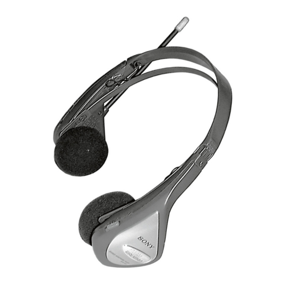
FM STEREO/AM HEADPHONE RADIO
SRF-H3
Australian Model
Advertisement
Table of Contents

Related Manuals for Sony SRF-H3


Summary of Contents for Sony SRF-H3
- Page 1 SRF-H3 SERVICE MANUAL Australian Model Ver 1.0 2000. 07 SPECIFICATIONS Frequency range: FM: 87.6 – 108 MHz AM: 530 – 1 710 kHz Power output: 5.0 mW + 5.0 mW (at 10 % harmonic distortion) Headphone type: Dynamic Power requirements: 1.5 V DC, one size AAA (R03) battery...
-
Page 2: Section 1 General
Replace the battery when the sound becomes weak or distorted. Remove the old battery and Driver insert a new one. units TUNE POWER Battery life (approximate hours) Sony Sony alkaline size AAA size AAA (R03) Dial scale (LR03) FM reception... -
Page 3: Section 2 Disassembly
Precision screwdriver 2 Push this portion down. Cabinet rear (R) assy 1 Unsolder two lead wires. 2-3. GEAR (TUNING) INSTALLATION Model name (SRF-H3) Gear (tuning) 1 Turn CV1 fully in the direction of arrow. Cabinet rear (R) assy — 3 —... -
Page 4: Section 3 Electrical Adjustments
SECTION 3 ELECTRICAL ADJUSTMENTS [FM] FM VCO Adjustment Setting: Procedure: BAND switch : FM FM RF signal generator FM RF signal generator 0.01 µF 0.01 µF Carrier frequency: 98 MHz Modulation: no modulation 75 kHz frequency deviation Output level: 0.1 V (100 dB) by 1 kHz signal. - Page 5 SRF-H3 SECTION 4 DIAGRAMS 4-1. BLOCK DIAGRAM FM/AM AM FREQ. COVERAGE FRONT END IC1(1/3) B+(R16) AM AGC BAND AM OSC CV1-4 AM OSC VCC1 SENS CT1-4 AM B+ LOCAL AM TRACKING S1-2 B+(R16) AM IF BUFFER STEREO MPX AM MIX...
- Page 6 SRF-H3 4-2. SCHEMATIC DIAGRAM — 7 — — 8 —...
-
Page 7: Printed Wiring Board
SRF-H3 4-3. PRINTED WIRING BOARD • Semiconductor Location Ref. No. Location D-10 — 9 — — 10 —... -
Page 8: Section 5 Exploded Views
SECTION 5 SECTION 6 AUDIO TUNER EXPLODED VIEWS ELECTRICAL PARTS LIST NOTE: NOTE: • -XX, -X mean standardized parts, so they may • The mechanical parts with no reference number • Due to standardization, replacements in the • CAPACITORS: • SEMICONDUCTORS have some differences from the original one. -
Page 9: Accessories And Packing Materials
TUNER Ref. No. Part No. Description Remarks < TRANSISTOR > 8-729-109-44 TRANSISTOR 2SK94 < RESISTOR > 1-216-295-00 SHORT 1-216-045-00 METAL CHIP 1/10W 1-216-295-00 SHORT 1-216-021-00 METAL CHIP 1/10W 1-216-035-00 METAL CHIP 1/10W 1-216-017-91 RES-CHIP 1/10W 1-216-043-91 RES-CHIP 1/10W 1-216-296-91 SHORT 1-216-295-00 SHORT 1-216-009-00 RES-CHIP 1/10W... - Page 10 SRF-H3 Sony Corporation 2000G16024-1 Audio Entertainment Group 9-927-940-31 Printed in Japan ©2000.7 — 14 — Published by PE General Engineering Dept.
Need help?
Do you have a question about the SRF-H3 and is the answer not in the manual?
Questions and answers