
Related Manuals for JVA ZLM4


Summary of Contents for JVA ZLM4
- Page 1 ZLM4 OEM Technical Manual Version 5, March 2021 © JVA Technologies Pty Ltd Page 1 of 32 Issue:3/03/2021 9:39:00 AM OEM technical manual.docx...
-
Page 2: Table Of Contents
Fence Wiring ............................... 19 Keypad Bus Wiring .............................. 20 Example group wiring diagrams .......................... 21 Z28 and two ZLM4 connected to Perimeter Patrol through a PAE223 (USB Interface) ........21 TECHNICAL INFORMATION ............................. 22 LCD Error messages ............................... 22 PROGRAMMING OPTIONS ............................22 Enter Programming mode ............................ - Page 3 Keys used for changing messages: ........................31 To Exit Keypad Programming ..........................31 Connecting Multiple Keypads to a system ......................31 Notes Regarding Keypad Configuration ......................... 32 © JVA Technologies Pty Ltd Page 3 of 32 Issue:3/03/2021 9:39:00 AM OEM technical manual.docx...
-
Page 4: Introduction
INTRODUCTION The ZLM4 is a 4 zone low voltage electric fence monitor. The ZLM4 may be used by itself or in conjunction with a number of high voltage security electric fence energisers. The ZLM4 monitors up to 4 loops of fence wire, each up to several hundred meters long, to detect someone tampering with the fence by cutting or shorting the wires. -
Page 5: Features
The maximum series resistance of the fence wire loop which can be accurately monitored is 5000 Ohms • * Not all versions of the PAE212, PAE224 or PAE218 GSM module recognise the ZLM4. For compatibility please check with your distributor or JVA •... -
Page 6: Equipment Requirements And Options
1. While the Keypad is not essential for normal operation, it is required to adjust the programmable options. 2. Up to 3 Keypads may be connected in parallel on a ZLM4, each Keypad must have a unique ID setting. 3. The ZLM4 contains patent pending technology, contact JVA for more information. -
Page 7: Operation
Status LED Lights The status LED’s on the front of the ZLM4 allow the user to quickly ascertain the current status of the unit and if any action needs to be taken. Below is a brief description of each LED (top to bottom) and the information it conveys. -
Page 8: Zlm4 Lcd Screen
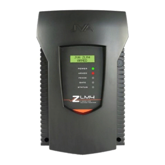
ZLM4 LCD Screen The ZLM4 will show the status on the optional LCD display. When disarmed JVA ZLM4 Disarmed While armed, the LCD display cycles the following information. 1:35V 2:37V ZLM4 Armed Battery 14.5V AC On 2:40V 4:35V All clear Pressing # on the keypad will freeze the current information displayed on the LCD screen for approximately 10 pulses. -
Page 9: Control Options
Control inputs The ZLM4 may have a single Key switch mounted on the right hand side of the cabinet which may be used to arm and disarm the security electric fence to which it is connected. This switch is useful for the simplest implementations where no keypad or PC control program is used. -
Page 10: Keypad Versions
3) A high voltage wire shorts to a low voltage wire (HV Short) Note: If the ZLM4 is monitoring a fence that has a disarmed energiser on it, a ground alarm will occur when one of the HV wires touches a LV wire. This is because the ZLM4s pulse will ground through the energisers transformer. -
Page 11: To Silence The Alarm
1 2 3 4 * 0 # 8 0 1 5 # * # Standby Battery Should there be a loss of mains power, the Power light on the keypad will go off. The status LED on the ZLM4 front panel will flash twice and the Keypad will show Trouble – AC Fail. -
Page 12: Zlm4 Relevant Keypad Codes
ZLM4 Relevant Keypad Codes Function Key Sequence Arm/Disarm [User PIN][#] Silence an alarm (Single zone system only) [User PIN][#] Start Programming the Z series energiser [Installer PIN][*] [0] [#] Start Programming the Keypad [Installer PIN][*] [0] [1] [#] Exit Programming (any mode) -
Page 13: Specifications
Note 3: This is the limit for the combination of the loads on both the “Siren” and “Strobe” outputs. Note 4: This is the maximum rating of the energiser if the ZLM4 is used on the same fence as a high voltage electric fence energiser. -
Page 14: Installation
Design and build the fence. (Beyond the scope of this manual.) Ask your distributor for help if required. Decide where the energiser, ZLM4 and Keypad are to be mounted. If on an external wall it should be housed within a weatherproof equipment box, shaded from direct sun. -
Page 15: Jumper Configuration
Jumper Configuration The ZLM4 is equipped with three jumpers, two of which (J3 and J4) operate in an identical fashion to those on the Z14. The third jumper, J8 will suppress the beeper on the ZLM4 when fitted. These are located in the top left corner of the PCB. -
Page 16: Control, Power And Io Terminals
Short these two contacts to provide +12v power to the common contact of Relay 6.* *+12v power limited to a maximum of 30W combined for relays 3-6, including Siren and Strobe outputs. © JVA Technologies Pty Ltd Page 16 of 32 Issue:3/03/2021 9:39:00 AM OEM technical manual.docx... -
Page 17: Fence Wiring Diagrams
Fence Wiring Diagrams Standalone fence continuity monitor The ZLM4 may be used to monitor a loop of wire on or under a perimeter fence. • Bare conductors on insulators as per high voltage electric fence, but powered by the ZLM4 low voltage monitor for sensitive environments such as public areas. -
Page 18: Low Voltage Zoning System
Low Voltage Zoning System The ZLM4 uses interleaved low voltage wires of the fence to detect any tampering. © JVA Technologies Pty Ltd Page 18 of 32 Issue:3/03/2021 9:39:00 AM OEM technical manual.docx... -
Page 19: Wiring Diagrams
Combining the ZLM4 with a Z Series energiser A ZLM4 can be combined with JVA Z series energisers to power the fence. The ZLM4 should be configured as a slave and the Z series energiser as the master. The number of Z series energisers and ZLM4 is limited by the available ID numbers if using the keypad bus, it is unlimited if using TCP/IP. -
Page 20: Keypad Bus Wiring
Set the Group ID of the ZLM4 to Slave 1 (2602#) The Group ID of the ZLM4 must be 1 value higher than the Group ID of the Z-Series Energiser driving it A ZLM4 by itself does not require the Group ID to be configured as it is factory set to Stand-Alone mode ©... -
Page 21: Example Group Wiring Diagrams
Example group wiring diagrams Z28 and two ZLM4 connected to Perimeter Patrol through a PAE223 (USB Interface) • Set the Group ID of the Z28 to Master (2601#) • Set the Group ID of the first ZLM4 to Slave 1 (2602#) •... -
Page 22: Technical Information
LCD Error messages The ZLM4 has the ability to display error messages. At start up if any of the Power On Self Tests (POST) fail an error message will be displayed after the version number. If these are “non-fatal” the ZLM4 will continue through start-up and be ready to run. -
Page 23: To Exit Programming Mode
To enter a new installer pin, press 00 followed by the new 6 digit PIN, then the key. If you cannot remember your installer or user PIN, return the ZLM4 memory to default. To do this, remove power (AC off and disconnect the battery), open the ZLM4 enclosure, remove jumper J4 and reconnect the battery for about 10 seconds. -
Page 24: Programmable Options Table
If used as part of a group, this sets the device ID Relay 6 Used to assign an alarm function to relay 6 (Zone 4 alarm) © JVA Technologies Pty Ltd Page 24 of 32 Issue:3/03/2021 9:39:00 AM OEM technical manual.docx... -
Page 25: Programming Options In Detail
General 9.5 V alarm. 10.0 V 10.5 V 11.0 V 11.5 V 12.0 V 12.5 V 13.0 V 13.5 V © JVA Technologies Pty Ltd Page 25 of 32 Issue:3/03/2021 9:39:00 AM OEM technical manual.docx... -
Page 26: Siren On Time (08X#)
NO Normally open NC Normally Closed Input 2 Function (12x#) This input cannot be configured to anything other than a ‘Gate’ input at this time. © JVA Technologies Pty Ltd Page 26 of 32 Issue:3/03/2021 9:39:00 AM OEM technical manual.docx... -
Page 27: Gate Delay (13X#)
1.2) +8 Disable Cross Couple Alarms [see section 3.1] (added in version 1.33) Zones (not yet implemented) This Option sets the amount of Zones the ZLM4 will monitor. This will reduce the Value Function amount of unnecessary information that will be displayed if you are only None monitoring one zone. -
Page 28: Auto Re-Arm Time (20X#)
A setting of 9 will disable auto re-arm. 3 Minutes The default is 0 Seconds (Immediate). 4 Minutes 5 Minutes 6 Minutes 7 Minutes Disabled – Do not auto rearm © JVA Technologies Pty Ltd Page 28 of 32 Issue:3/03/2021 9:39:00 AM OEM technical manual.docx... -
Page 29: Relay Functions
Alarm Function Logic for alarm state (opposite of normal state) Zone x The ZLM4 is Armed AND Alarm Any zone alarm occurs, these include: The loop return Voltage has fallen below the Fence Voltage Alarm Level (Low Voltage) High voltage has been detected (shorted to high voltage wires) for more Energiser pulses than the Missed Pulse Count setting. -
Page 30: Group Mode (26X#)
Keypad bus into a group. Slave 4 Slave 5 The ZLM4 should only be a group master if there are no Z energisers in the Slave 6 group. I.e. the group is made up of one or more ZLM4’s only. -
Page 31: Keypad Programming
Energiser. After a reset, the Energiser will determine what Keypads are connected, and only these ADDRESSES will be used in the future. This prevents un-authorised Keypads being added to the system once it is running. © JVA Technologies Pty Ltd Page 31 of 32 Issue:3/03/2021 9:39:00 AM... -
Page 32: Notes Regarding Keypad Configuration
When re-analysing a group ensure all energisers are disarmed. If they are not this function will not work properly. Note: If the group ID has recently been changed you may need to reset ([PIN]*68#) before the new ID’s will be properly reported to the keypad. © JVA Technologies Pty Ltd Page 32 of 32 Issue:3/03/2021 9:39:00 AM...
Need help?
Do you have a question about the ZLM4 and is the answer not in the manual?
Questions and answers