Table of Contents
Advertisement
Advertisement
Table of Contents

Related Manuals for Powersmart DB8620


Summary of Contents for Powersmart DB8620
- Page 1 INSTRUCTION MANUAL 20" 3-in-1 Self Propelled Lawn Mower Model # DB8620 Have product questions or need technical support? Please feel free to contact us! Website: www.Amerisuninc.com www.powersmartusa.com Toll free: 1-800-791-9458 Mon-Fri 9-5 EST Email: support@amerisuninc.com...
-
Page 3: Table Of Contents
Storage……………………………………………………………………. 16 Troubleshooting…………………………………………………………. Exploded view & parts list……………………………………………… Warranty………………………………………………………………… TECHNICAL DATA 20" 3-in-1 Self Propelled Lawn Mower Model # DB8620 Engine type: 4 stroke, OHV, single cylinder with forced air cooling system Displacement: 196 cc Fuel tank capacity: 0.9 Gallon Oil capacity: 20 fl.oz... -
Page 4: Introduction
INTRODUCTION ® Thank You for Purchasing a PowerSmart Product. This manual provides information regarding the safe operation and maintenance of this product. Every effort has been made to ensure the accuracy of the ® information in this manual. PowerSmart reserves the right to change this product and specifications at any time without prior notice. -
Page 5: General Safety Procedures
GENERAL SAFETY PROCEDURES For any questions regarding the hazard and safety notices listed in this manual or on the product, please call (800) 791-9458 Mon-Fri 9-5 EST before using the engine. DANGER: CARBON MONOXIDE Using an engine indoors CAN KILL YOU IN MINUTES. Engine exhaust contains carbon monoxide (CO). -
Page 6: Important Safety Instructions
IMPORTANT SAFETY INSTRUCTIONS General Operation Read, understand, and follow all instructions on the machine and in the manual(s) before starting. 1. Do not put hands or feet near or under the machine. Keep clear of the discharge opening at all times. 2. - Page 7 4. Use extra care when approaching blind corners, shrubs, trees, or other objects that may block your view of a child. Service 1. Safe Handling of Gasoline 2. To avoid personal injury or property damage, use extreme care in handling gasoline. Gasoline is extremely flammable and the vapors are explosive.
-
Page 8: Knowing Your Lawn Mower
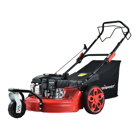
KNOWING YOUR LAWN MOWER Please use the illustration below to familiarize yourself with the location and function of the components that control of your lawn mower. Recoil Starter handle Fuel tank cap Grass catcher Rear discharge door Rear wheel Lower handle Cutting height adjustment lever Quick handle lock lever Oil dipstick... -
Page 9: Lawn Mower Preparation
LAWN MOWER PREPARATION The following section describes steps necessary to prepare the lawn mower for use. If after reading this section, you are unsure about how to perform any of the steps please call (800) 791-9458 Mon-Fri 9-5 EST for customer service. Failure to perform these steps properly can damage the lawn mower or shorten its lifespan. - Page 10 ATTACH THE FRONT WHEEL ASSEMBLY The front wheel assembly attaches to the front of the deck. To attach the front wheel to the deck, perform the following steps: 1. Mount the single wheel to the wheel bar with the mounting screw. 2.
-
Page 11: Grass Catcher
GRASS CATCHER Attach grass catcher 1. Lift mower rear discharge door. 2. Place grass catcher into the slots in the handle brackets. 3. Release the rear discharge door so that it rests on the grass catcher. Caution: Make sure that the mulch plug adapter has been removed from of the rear deck door’s opening. -
Page 12: Operation
ADJUSTING THE CUTTING HEIGHT Warning! Cutting height adjustments should only be performed after the engine and blades have come to a complete stop! It is always best to begin cutting your lawn with a higher deck height to prevent scalping your lawn. Rear wheel The cutting height for the rear wheels is adjusted with a single lever. -
Page 13: Engine Start/Stop Lever
ENGINE START/STOP LEVER Engine start/stop lever This lawn mower comes equipped with an engine start/stop lever to prevent unintentional starting and to ensure safe operation. Releasing this lever will quickly stop the blade in case of danger. The lever must be actuated before the lawn mower is started. - Page 14 It’s import to keep the underside of the mower deck clean and remove grass build-up. This buildup will decrease mulching quality, and make it harder for the equipment to bag the grass. Always mow along inclines (not up and down). You can prevent the lawn mower from slipping down by holding a position at an angle upwards.
-
Page 15: Maintenance
MAINTENANCE Proper routine maintenance of this mower will help prolong the life of the machine. Always observe safety rules when performing any maintenance. The warranty on this lawn mower does not cover items that have been subjected to operator abuse or negligence. -
Page 16: Storage
RECCOMENDATIONS FOR OFF SEASON STORAGE CAUTION: Never place any type of storage cover or tarp on the MOWER while it is still hot. If the MOWER is being stored for short periods of time (30 to 60 days), add stabilized fuel to the gas tank until it is full. -
Page 17: Troubleshooting
TROUBLESHOOTING Problem Cause Solution Engine fails to start Engine start/stop lever Engage engine start/stop lever. disengaged. Spark plug wire disconnected. Connect spark plug wire. Fuel tank empty or stale fuel. Fill tank with clean, fresh gasoline. Engine not primed. Press primer bulb. Faulty spark plug. - Page 18 EXPLODED VIEW AND PARTS LIST Handle Assembly Item Stock# Description Item Stock# Description 1 303080465 Engine control lever 13 303160611A Screw 2 303070984A Upper handle 14 303010269 Screw 3 302020019A Sponge foam 15 303070983A Upper handle base 4 303080466 Drive control bar 16 303030036 Nylon nut M8 5 303020502...
- Page 19 Deck Assembly Item Stock# Description Item Stock# Description 303180891A Grass catcher bracket 303042023 Flat washer 302120035 Grass catcher 303041022 Washer 8 203050264 Rear discharge cover 303020124 Bolt M8x35 303070976A Mulching adapter 303160608A Driving pulley 303030032 Nylon nut M6 303110040 Woodruff key Square neck bolt 203050346A Rear cover shaft 303020163...
- Page 20 Drive Assembly Item Stock# Description Item Stock# Description 203050344A Wheel cover 303020339 Bolt M6x14 303030036 Nylon nut M8 303130322 Tension spring 203040021A Wheel 302040067 V-belt 203010806A Dust cover 303160607A Gear box spring 303160470 Gear Right 303240487A Gear box assembly 303060104A Adjustment plate 303123017A Cylindrical pin 303020468...
- Page 21 Front Wheel Assembly Item Stock# Description Item Stock# Description Square neck bolt 303020503 Bolt M6x35 303020167 M6x36 303020282 Bolt M6x16 303160617A Front wheel stents Square neck bolt 303041009 Spring washer 6 303020384 M8x95 303042021 Flat washer 6 303050007 Collar 12 303070978 Mounting plate 303060103A Front wheel sleeve...
- Page 22 To make a claim under this Limited Warranty, you must return the entire power tool product; transportation prepaid, to PowerSmart. The owner must include a legible copy of the original receipt, which shall list the date of purchase, along with the company’s name where the product was purchased.
Need help?
Do you have a question about the DB8620 and is the answer not in the manual?
Questions and answers